
Diagnosis device and diagnosis method for temperature sensor of automatic transmission

A technology for temperature sensors and automatic transmissions, applied in multi-ratio transmissions, transmission control, vehicle gearboxes, etc., can solve problems such as increased driver discomfort, deterioration of automatic transmission status, and inability to perform double fault detection

Active Publication Date: 2021-11-09
JATCO LTD +1
View PDF9 Cites 0 Cited by
  • Summary
  • Abstract
  • Description
  • Claims
  • Application Information

AI Technical Summary

Problems solved by technology

However, when diagnosing malfunctions by comparing the values ​​of two sensors, double failures cannot be detected because the comparison object has already failed at the time of abnormality diagnosis.
However, if the abnormality countermeasure based on the speed change restriction is immediately started from the time when the abnormality of the temperature sensor is diagnosed, the drivability at the time of failure will be deteriorated.
On the other hand, if the standby is performed so that the abnormality countermeasures based on the speed change limitation are not entered even if a functional abnormality is diagnosed, if a double fault occurs during the standby, since the functional abnormality of the second temperature sensor cannot be detected, Therefore, it is impossible to shift to a limp home fixed at a predetermined gear, and the state of the automatic transmission deteriorates, which may increase the discomfort to the driver.

Method used


Image

  • Diagnosis device and diagnosis method for temperature sensor of automatic transmission
  • Diagnosis device and diagnosis method for temperature sensor of automatic transmission
  • Diagnosis device and diagnosis method for temperature sensor of automatic transmission

Examples


Embodiment Construction

[0029] Hereinafter, an embodiment of the temperature sensor diagnostic device for an automatic transmission according to the present invention will be described based on an embodiment shown in the drawings.

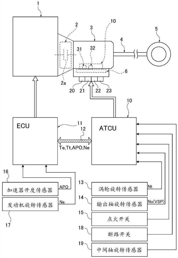
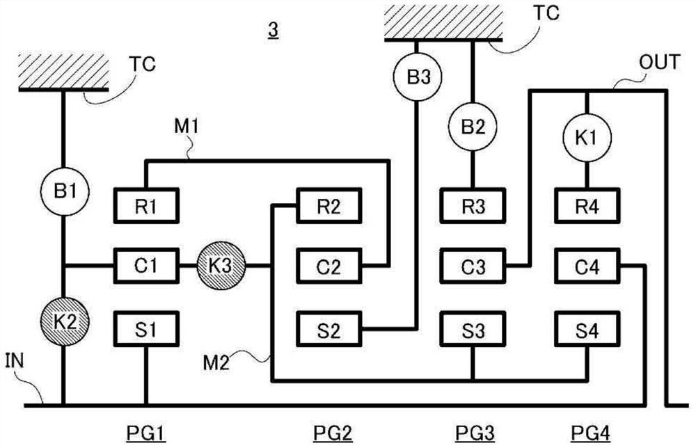
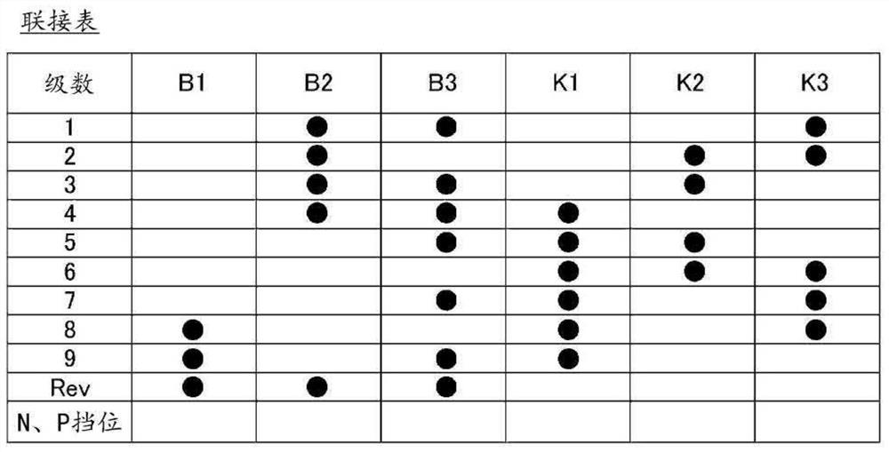
[0030] The temperature sensor diagnosis device in the embodiment is applied to an engine vehicle (an example of a vehicle) equipped with an automatic transmission having 9 forward speeds and 1 reverse speed. Hereinafter, the structure of the embodiment is divided into "overall system structure", "detailed structure of automatic transmission", "detailed structure of hydraulic control system / electronic control system", and "diagnostic processing structure of substrate temperature sensor".

[0031] (overall system structure)

[0032] figure 1 It is an overall system diagram showing an engine vehicle equipped with an automatic transmission to which the temperature sensor diagnostic device of the embodiment is applied. Below, based on figure 1 Describe the overall system st...


PUM


Abstract

A substrate temperature sensor as an AT control unit (10) has a main substrate temperature sensor (31) and a sub-substrate temperature sensor (32) as substrate temperature sensors of an AT control unit (10). A substrate temperature sensor diagnosis controller (100) assesses whether or not a main temperature sensor value (MA1) and a sub-temperature sensor value (SUB1) have diverged by at least a prescribed value, and upon assessing that a state of divergence by at least a prescribed value is continually ongoing for at least a prescribed time, diagnoses that one of the substrate temperature sensors (31, 32) has an anomaly. For a prescribed interval depending on a predetermined condition after the anomaly diagnosis, a torque limit is imposed, the torque limit limiting input torque from an engine (1) to an automatic transmission (3). When the anomaly detection of the substrate temperature sensors (31, 32) is ongoing even when the prescribed interval has ended, transmission limiting of the automatic transmission (3) is performed in addition to the imposing of the torque limit.

Description

technical field [0001] The present invention relates to a temperature sensor diagnosis device and a diagnosis method of an automatic transmission mounted on a vehicle. Background technique [0002] Conventionally, as a control device for a vehicle equipped with an automatic transmission, a well-known vehicle control device includes: a transmission cooling system diagnostic unit that compares the transmission oil temperature with a judgment threshold to diagnose abnormalities in the transmission cooling system; The transmission cooling system diagnosis means changes the shift mode of the automatic transmission to a high speed side or fixes it to a predetermined level when the transmission cooling system is diagnosed to be abnormally high temperature (see Patent Document 1). [0003] In the conventional device described above, it is impossible to determine whether the temperature is high when the temperature sensor fails, so it is considered to be fixed at a predetermined gear...

Claims


Application Information

Patent Timeline
IPC IPC(8): F16H59/68F16H63/50F16H61/12F16H61/16F02D45/00
CPCF16H61/16F02D45/00F16H61/12F16H63/50F16H2200/2012F16H2200/2046F16H2200/0065F16H2061/1284F16H2061/122F16H2061/124F16H2061/1208F16H2061/163F16H2063/508F16H59/72F16H61/0006F16H2061/1212F16H2061/1292
Inventor 滨野正宏村瀬安范
Owner JATCO LTD
Learn More