
Corneal perception instrument

A corneal perception and angle technology, applied in medical science, sensors, diagnostic recording/measurement, etc., can solve the problems of lack of operation consistency, damage to corneal epithelial cells, false positive blink reflex, etc., to improve operation consistency and measurement Accuracy, reducing the likelihood of false positives, reducing the effect of visual distraction factors

Pending Publication Date: 2021-11-12
TONGJI HOSPITAL ATTACHED TO TONGJI MEDICAL COLLEGE HUAZHONG SCI TECH
View PDF0 Cites 0 Cited by
  • Summary
  • Abstract
  • Description
  • Claims
  • Application Information

AI Technical Summary

Problems solved by technology

[0004] In practice, it is found that the Cochet Bonnet keratometer mainly has the following problems: 1) Lack of operational consistency: the instructions require whether the subject can feel when there is a 5° bend. This angle is not easy to grasp, and when the patient cannot cooperate well , there is a large difference in the measurements of different operators
2) The fiber touches the cornea from the front, which may damage the corneal epithelial cells and cause the risk of secondary microbial infection
3) Fiber filaments are reused, and there is a risk of cross-infection between people or between eyes
4) The fiber filaments approach the eyes from the front. In addition to tactile stimulation, there is also visual interference, and there is a greater possibility of false positives of the blink reflex.
5) The measurement results are measured by the length of the fiber. Since there is no linear correlation between the length of the fiber and its hardness, it is impossible to compare the relative value of the difference between different patients, so that it is impossible to quantify the degree of corneal sensory loss (percentage or fractional relationship )

Method used


Image

  • Corneal perception instrument
  • Corneal perception instrument
  • Corneal perception instrument

Examples


Embodiment 1

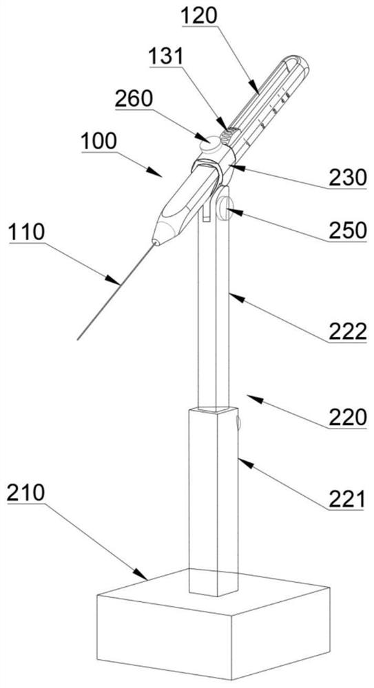
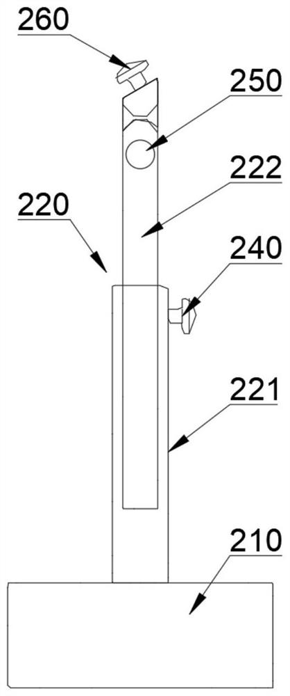
[0042] like Figure 1 ~ 7 As shown, the present embodiment provides a corneal sensor including the handle kit 100 and the lateral downward pressure adjustment kit 200; the handle kit 100 includes a handle 120 and a fiber wire 110 in the handle 120; lateral down pressure The adjustment kit 200 is used to move the handle kit 100 to make the front end of the fiber wire 110 with the patient's horizontal line pressure patient eye 300.

[0043] In this example, the value is 30 °, or other suitable angle can be selected in the range of 10 ° to 80 °, such as 10 °, 20 °, 30 °, 40 °, 50 °, 60 °, 70 °, 80. °, etc., which is better in the range of 20 ° ~ 40 °.

[0044] In order to adjust the effective wire of the fiber wire 110 (i.e., a free segment length of the decompression), the cornea sensor provided in this example further includes a valid wire long adjustment mechanism 130 that projects the handle 120 for the fiber wire 110. Effective wire long L is adjusted.

[0045] In order to indicate...

Embodiment 2

[0061] like Figure 10 , 11 As shown, the scheme is further improved on the basis of Example 1 (the same is no longer illustrated):

[0062] The middle portion of the handle 120 is integrally provided with a rotary connection head 230, and is hinged from the slider 222. Both ends of the handle 120 are provided with a hollow cavity 121, and the slider cavity 122 is located in the middle of the hollow cavity 121; the lower portion of the slider 132 is sandwiched in the middle of the fiber wire 110, which can drive the fiber wire 110 to the handle 120 ends. Eneendive end moves and projects from the hollow cavity 121 of the same end to perform measurement.

[0063] In order to indicate the perception level on both sides, the effective wire long indication mark 126 is set to a symmetrical scale, sequentially 1, 2, 3, 4, 5, 4, 3, 2, 1, and specific scale division. Example 1.

[0064] This embodiment can achieve a filament detection of both eyes, the measurement step is briefly described ...

Embodiment 3

[0071] like Figure 12 , 13 As shown, the scheme is further improved on the basis of Example 1 (the same is no longer illustrated):

[0072] The effective wire long adjustment mechanism 130 includes an adjustment lever 133, which is slidably coupled to the slide (not shown) set at the upper portion of the handle 120; the fiber wire 110 is fixed to the handle 120, and its end is disposed from the adjustment rod 133 or in the hollow cavity 121 disposed between the adjustment lever 133 and the handle 120.

[0073] In this embodiment, the hollow cavity 121 is combined with a complete circular cavity in combination of two semicircular grooves located at a lower portion of the adjustment lever 133 and at the upper portion of the handle 120. However, the hollow cavity 121 can also be fully disposed in the adjustment lever 133, at which time, the fiber wire 110 needs to be fixed to the handle 120 after assembly with the adjustment lever 133.

[0074] A fastener 123 is provided on the handl...


PUM


Abstract

The invention discloses a corneal perception instrument. The corneal perception instrument comprises a handle kit and a lateral pressing adjusting kit, wherein the handle kit comprises a handle and a fiber filament sleeved in the handle; the lateral pressing adjusting kit is used for moving the handle kit, so that the front end of the fiber filament and the horizontal sight line of a patient form an included angle alpha, the eyes of the patient are pressed downwards for measurement, and the included angle alpha is 10-80 degrees. With the corneal perception instrument, a doctor can judge the sensitivity of the corneal perception of the patient according to the pressure feeling of the patient to the tip end of the fiber filament, compared with the prior art, the operation consistency, the measurement accuracy and the safety are improved, and meanwhile, the possibility of false positive is reduced.

Description

Technical field [0001] The present invention relates to an apparatus for measuring corneal sensation. Background technique [0002] The cornea is feeling the most sensitive nerve sites, play an important role and perception of the risk of corneal tissue nutrition, stress can cause slight blink reflex reaction conditions. Patients suffering from sensory nerve damage eye diseases, and corneal sensitivity level of perception showed varying degrees of decline and even disappear. The worse the patient's perception, the lower the sensitivity of the cornea pressure, the better the patient's perception, the higher the sensitivity of the cornea pressure. [0003] Of corneal sensitivity were measured using the Cochet Bonnet's current corneal sensitivity meter, the measurement process is as follows: Let the patient sitting looking straight forward, touching the cornea with a vertical 0.11 mm diameter nylon line, until the wire becomes bent to just As can be seen camber (skew approximately 5...

Claims


Application Information

Patent Timeline
IPC IPC(8): A61B3/02A61B5/00
CPCA61B3/02A61B5/4005
Inventor 李贵刚徐玲娟王玮
Owner TONGJI HOSPITAL ATTACHED TO TONGJI MEDICAL COLLEGE HUAZHONG SCI TECH
Learn More