
Discharging mechanism of concrete processing equipment

A technology of processing equipment and discharging mechanism, which is applied in the direction of conveyor, packaging, loading/unloading, etc., which can solve the problem of the difficulty in accurately controlling the weight of concrete blanking, affecting the accuracy of concrete performance detection, and the difficulty of continuous quantitative and accurate discharge of concrete And other issues

Active Publication Date: 2021-11-12
桐乡市钟大建材有限公司
View PDF5 Cites 1 Cited by
  • Summary
  • Abstract
  • Description
  • Claims
  • Application Information

AI Technical Summary

Problems solved by technology

During the trial-manufacturing process of existing concrete, after the trial-manufacturing process is completed, the concrete in the concrete preparation kettle needs to be discharged into the trial-manufacture mold required for the test for later performance testing, and the same weight is mixed with ingredients to make It is necessary to set up multiple groups of test comparison groups for concrete. The existing concrete discharge mechanism mainly uses workers' manual or electric opening and closing valves to control the concrete blanking, which makes it difficult to accurately control the weight of concrete blanking, resulting in multiple test comparisons. The concrete weight of the group is different, it is difficult to realize the continuous quantitative and accurate discharge of concrete, which affects the accuracy of concrete performance detection and cannot meet the needs of processing and use.

Method used


Image

  • Discharging mechanism of concrete processing equipment
  • Discharging mechanism of concrete processing equipment
  • Discharging mechanism of concrete processing equipment

Examples


Embodiment Construction

[0015] In order to further describe the present invention, the specific implementation of a discharge mechanism of concrete processing equipment will be further described below in conjunction with the accompanying drawings. The following examples are explanations of the present invention and the present invention is not limited to the following examples.

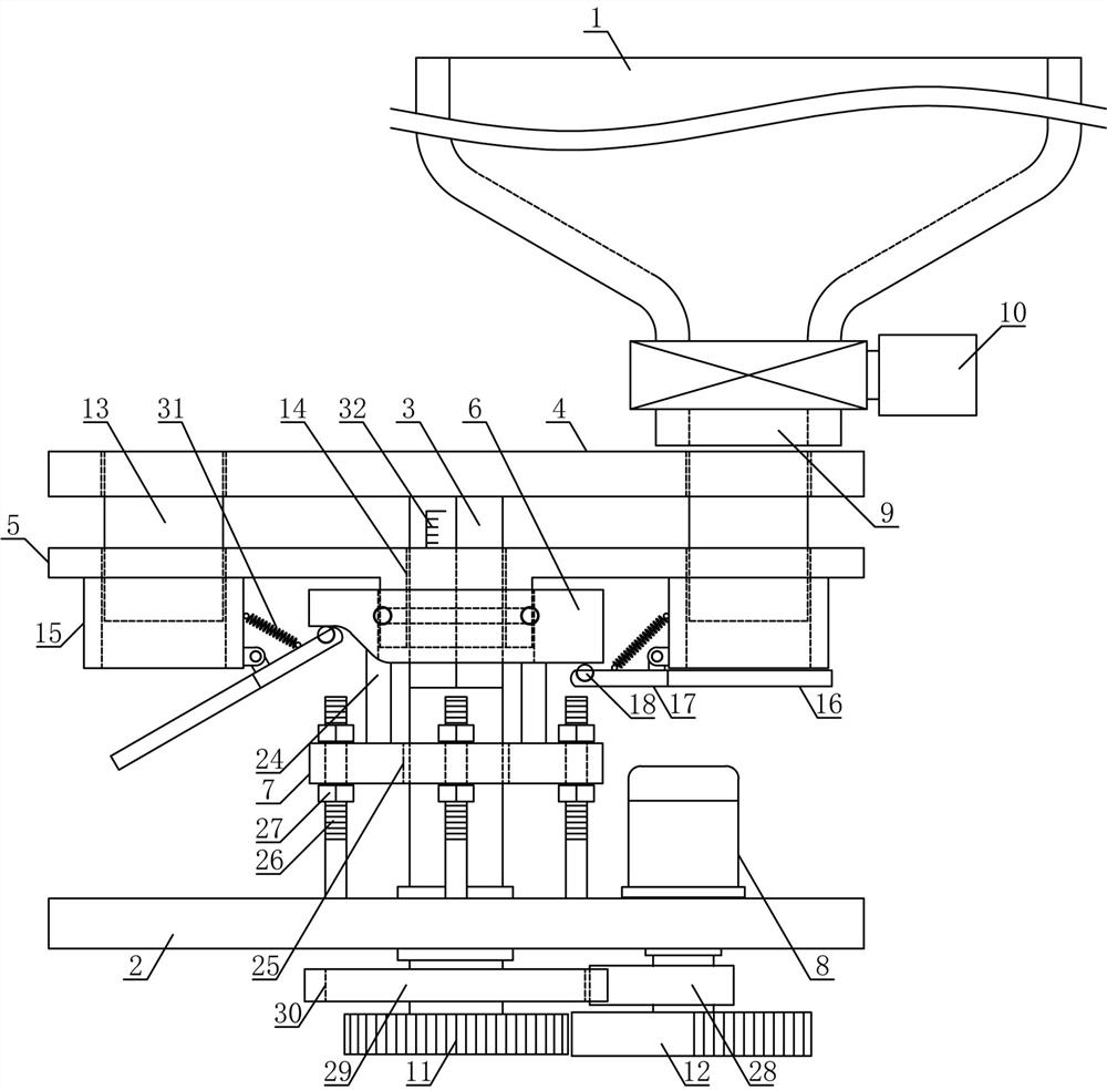
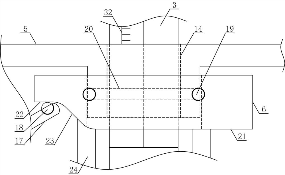
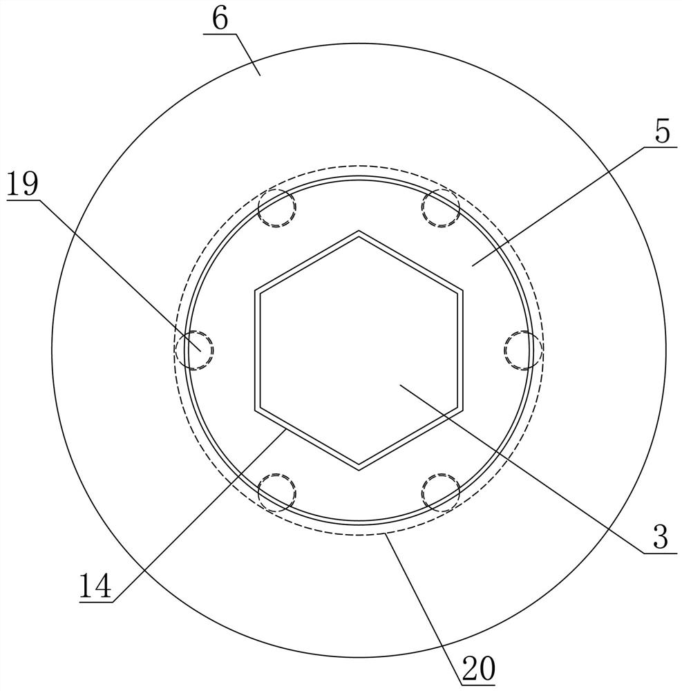
[0016] Such as figure 1 , figure 2 , image 3 and Figure 4 As shown, the discharge mechanism of a concrete processing equipment in the present invention includes a concrete preparation kettle 1, a discharge support base plate 2, a discharge vertical shaft 3, a discharge transfer circular plate 4, a lifting adjustment turntable 5, and a bottom cover limit The ring plate 6, the lifting adjustment plate 7 and the transfer discharge motor 8, the lower middle part of the concrete preparation kettle 1 are vertically connected with a concrete blanking pipe 9, and the concrete blanking pipe 9 is fixedly provided with a concrete ...


PUM


Abstract

The invention discloses a discharging mechanism of concrete processing equipment, and belongs to the field of mechanical equipment for building material processing. According to the discharging mechanism of the concrete processing equipment, a concrete blanking control valve is arranged on a concrete blanking pipe of a concrete production kettle, a discharging transferring gear is arranged at the lower end of a discharging vertical rotating shaft, a discharging driving gear at the output end of a transferring discharging motor is an intermittent gear, concrete discharging barrels are arranged at two sides of a discharging transferring circular plate respectively, lifting adjusting sleeves which match the concrete discharging barrels are arranged at two sides of a lifting adjusting rotary disc respectively, a bottom cover limiting annular plate is horizontally arranged at the lower side of the lifting adjusting rotary disc, the middle portion of the lower side of the lifting adjusting rotary disc is horizontally and rotatably connected with the inner side of the middle portion of the bottom cover limiting annular plate, and a lifting adjusting plate is horizontally arranged at the lower side of the bottom cover limiting annular plate. The discharging mechanism of the concrete processing equipment is reasonable in structural design, concrete can be subjected to continuous quantitative transferring and discharging, the single-time transferring and discharging amount of the concrete can be accurately adjusted, the automation degree of concrete discharging is improved, and the production and use requirements are met.

Description

technical field [0001] The invention belongs to the field of building material processing machinery and equipment, and in particular relates to a discharge mechanism of concrete processing equipment. Background technique [0002] Concrete refers to the collective name of engineering composite materials that aggregate aggregates into a whole by cementitious materials. Concrete is the main civil engineering material. It is composed of cementitious materials, granular aggregates, water, admixtures and blending ingredients. Concrete is an artificial building material prepared in a certain proportion, uniformly stirred, densely formed and cured. Concrete has the characteristics of rich raw materials, low price and simple production process, so its usage is increasing. Concrete is mainly divided into two stages and states: the plastic state before setting and hardening, that is, fresh concrete or concrete mixture, and the hard state after hardening, that is, hardened concrete or c...

Claims


Application Information

Patent Timeline
IPC IPC(8): B65D90/54B65D88/54B65D90/66B65G65/40
CPCB65D90/54B65D88/54B65D90/66B65G65/40B65G2201/045Y02W30/91
Inventor 黄清林姚晓光周弘韬梁化洋
Owner 桐乡市钟大建材有限公司
Learn More