Extraction device for rare earth hydrometallurgy

A technology of hydrometallurgy and extraction device, which is applied in mixers with rotary stirring devices, chemical instruments and methods, mixers, etc., can solve the problems of low mixing efficiency, complicated operation, insufficient mixing and extraction, etc., so as to improve the quality , the effect of rapid separation

Inactive Publication Date: 2021-11-12
王鲜
View PDF0 Cites 3 Cited by
  • Summary
  • Abstract
  • Description
  • Claims
  • Application Information

AI Technical Summary

Problems solved by technology

[0004] In order to overcome the shortcomings of the prior art, such as insufficient mixing and extraction, low mixing efficiency and complicated operation, the technical problem is to provide an extraction device for rare earth hydrometallurgy with relatively uniform mixing, high mixing efficiency and simple operation

Method used


Image

  • Extraction device for rare earth hydrometallurgy
  • Extraction device for rare earth hydrometallurgy
  • Extraction device for rare earth hydrometallurgy

Examples


Embodiment 1

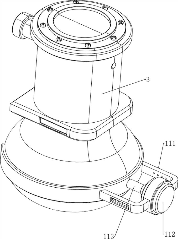
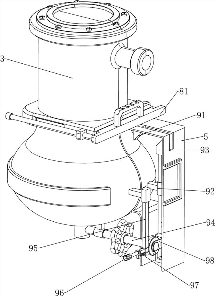
[0088] An extraction device for rare earth hydrometallurgy, such as Figure 1-7 As shown, it includes a base plate 1, a first bracket 2, a first material storage box 3, a feed frame 4, a mounting plate 5, a second bracket 6, a first valve 7, a material retaining mechanism 8 and a locking mechanism 9, and the base plate 1 is provided with a first support 2 on the rear side, and a first material storage box 3 is installed on the top of the first support 2. A feed frame 4 is provided on the upper front of the first material storage box 3. There is a mounting plate 5, the mounting plate 5 is connected with the first material storage box 3, the bottom of the first material storage box 3 is provided with a second support 6, the second support 6 is rotatably provided with a first valve 7, and the first material storage box 3 is provided with a blocking mechanism 8 in the middle, and the lower side of the mounting plate 5 is provided with a locking mechanism 9 .

[0089] When people ...

Embodiment 2

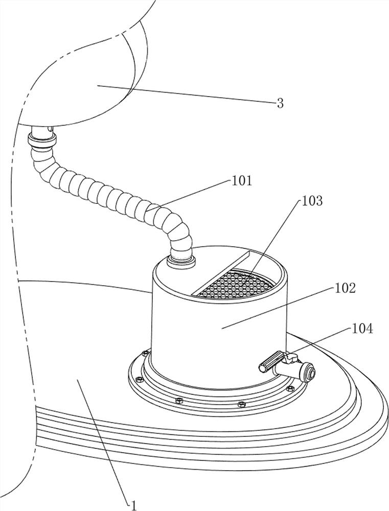
[0095] On the basis of Example 1, such as Figure 8-14 As shown, a filter mechanism 10 is also included, and the filter mechanism 10 includes a first hose 101, a second storage tank 102, a filter screen 103 and a second valve 104, and the second storage tank 102 is installed on the front side of the bottom plate 1 , the first hose 101 is connected between the lower part of the first material storage box 3 and the second material storage box 102, the upper part of the inner side of the second material storage box 102 is rotatably provided with a filter screen 103, and the lower part of the front side of the second material storage box 102 The rotary type is provided with a second valve 104 .

[0096] The rare earth elements flow forward and downward through the first hose 101, so as to flow into the filter screen 103, so that the rare earth elements are filtered, and then more pure rare earth elements are extracted, thereby ensuring the quality of the rare earth elements. After...


PUM


Abstract

The invention relates to a separation device, in particular to an extraction device for rare earth hydrometallurgy. The extraction device for rare earth hydrometallurgy, provided by the invention, is relatively uniform in mixing, high in mixing efficiency and simple to operate. The extraction device for rare earth hydrometallurgy comprises a bottom plate and a first support, a first storage box, a feeding frame, a mounting plate, a second support and a first valve; the first support is arranged on the bottom plate; the first storage box is mounted at the top of the first support; the feeding frame is arranged on the upper side of the first storage box; the mounting plate is arranged on the upper portion of the first support, and the mounting plate is connected with the first storage box; the second support is arranged at the bottom of the first storage box; and the first valve is rotationally arranged on the second support. By arranging a material blocking mechanism, when people pull the material blocking mechanism, rare earth and extracting materials flow downwards into the lower side of the first storage box; the rare earth is separated in the first storage box; and then the discharging effect is achieved.

Description

technical field [0001] The invention relates to a separation device, in particular to an extraction device for rare earth hydrometallurgy. Background technique [0002] Rare earth is the general name of seventeen metal elements including lanthanide, scandium and yttrium in the chemical periodic table. There are 250 kinds of rare earth ores in nature. The Finnish chemist Gadolin first discovered rare earth in 1799. In four years, the first rare earth "element" was isolated from a piece of heavy ore resembling asphalt. Because rare earth minerals were found in the eighteenth century, only chemical methods could be used to produce a small amount of water-insoluble oxides. In history, this kind of oxide is customarily called "earth", hence the name rare earth, the chemical reagent that the extractant can form an extract dissolved in the organic phase with the extractant, in hydrometallurgy, the extractant The function is to cooperate with the extracted metal to form an extract ...

Claims


Application Information

Patent Timeline
Patent Type & Authority Applications(China)
IPC IPC(8): C22B3/02C22B3/22C22B3/26C22B59/00B01F15/02B01F7/02
CPCC22B3/02C22B59/00C22B3/22Y02P10/20
Inventor 王鲜
Owner 王鲜
Why Eureka
Try Eureka