River channel dredging ship

A technology for dredging ships and river channels, applied in fixed filter element filters, mechanically driven excavators/dredgers, applications, etc., can solve problems such as cutting underwater aquatic plants and other entanglements, and achieve self-cleaning ability. The effect of improving efficiency and reducing workload

Inactive Publication Date: 2021-11-12
唐志奇
View PDF1 Cites 1 Cited by
  • Summary
  • Abstract
  • Description
  • Claims
  • Application Information

AI Technical Summary

Problems solved by technology

[0006] Aiming at the deficiencies of the prior art, the present invention provides a river dredging ship, which solves the problem that the device cannot cut underwater aquatic plants and other entanglements when clearing the silt in Hanoi, and effectively guarantees the dredging work The normal operation of the device improves the desilting efficiency of the device, ensures the self-cleaning ability of the device during operation, reduces the workload of manual cleaning in the later stage, achieves the purpose of filtering the pumped river water, and effectively improves the collection efficiency. Efficiency of frame loading

Method used


Image

  • River channel dredging ship
  • River channel dredging ship
  • River channel dredging ship

Examples


Embodiment 1

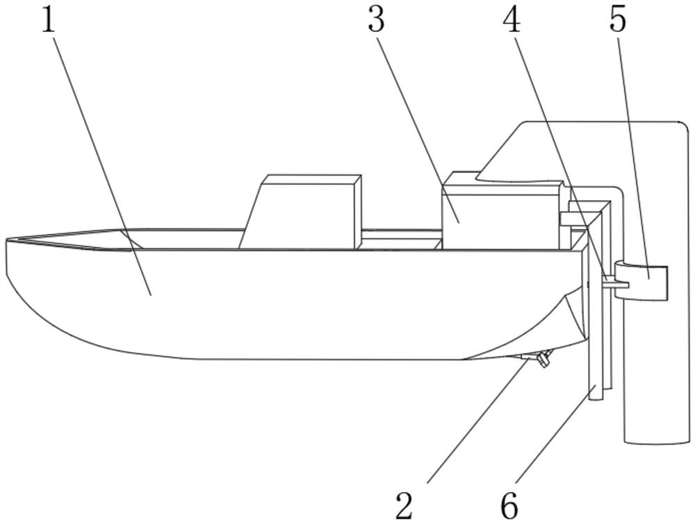
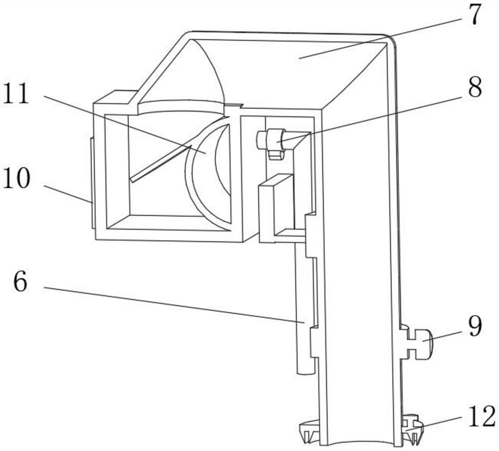
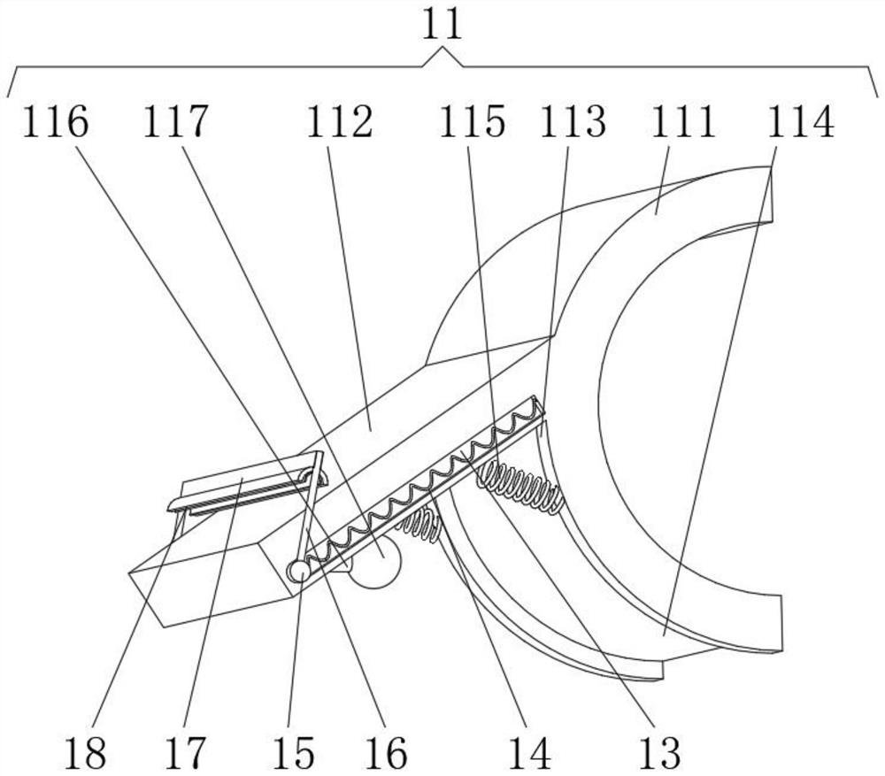
[0027] see Figure 1-3 , the present invention provides a technical solution: a river dredging ship, comprising a hull 1, a driving propeller 2 is installed at the bottom of the hull 1, a collection frame 3 is fixedly connected to the inner side of the hull 1, and a fixing plate is fixedly connected to the outer side of the hull 1 4. The side of the fixed plate 4 far away from the hull 1 is fixedly connected with an arc-shaped stop clamp 5, the side of the collection frame 3 close to the fixed plate 4 is connected with a water outlet pipe 6, and the top of the collection frame 3 is connected with a feed pipe 7, A suction pump 8 is installed on the outside of the outlet pipe 6 close to the collecting frame 3, a dredging pump 9 is installed on the outside of the feed pipe 7 away from the collecting frame 3, and a retrieving pump is installed on the side of the collecting frame 3 away from the outlet pipe 6. Door 10, filter device 11 is installed on the inner wall of collection f...

Embodiment 2

[0034] see Figure 1-5 , the present invention provides a technical solution: on the basis of Embodiment 1, a crushing device 12 is installed near the position of the dredging pump 9 on the outside of the feed pipe 7, the crushing device 12 includes a rotating motor 121, and the output shaft of the rotating motor 121 Rotationally connected with a rotating rod 122, the end of the rotating rod 122 away from the rotating motor 121 is fixedly connected with a circular plate 123, one side of the circular plate 123 is provided with a groove 124, and the inner wall of the groove 124 is evenly equipped with elastic columns 125, the elastic force An arc-shaped push plate 126 is fixedly connected to an end of the post 125 away from the groove 124 .

[0035] A base plate 19 is evenly installed on the side of the circular plate 123 away from the rotating rod 122, and a cylinder 20 is fixedly connected to the side of the base plate 19 away from the circular plate 123. The outer side of the...


PUM


Abstract

The invention discloses a river channel dredging ship, and relates to the technical field of desilting. The river channel dredging ship comprises a ship body, wherein a driving propeller is installed at the bottom of the ship body, a collecting frame is fixedly connected to the inner side of the ship body, a fixing plate is fixedly connected to the outer side of the ship body, an arc-shaped limiting clamping plate is fixedly connected to the side, away from the ship body, of the fixing plate, the side, close to the fixing plate, of the collecting frame communicates with a water outlet pipe, the top of the collecting frame communicates with a feeding pipe, a water suction pump is installed at the position, close to the collecting frame, of the outer side of the water outlet pipe, a mud suction pump is installed at the position, away from the collecting frame, of the outer side of the feeding pipe, a material taking door is installed on the side, away from the water outlet pipe, of the collecting frame, and a filtering device is mounted on the inner wall of the collecting frame. According to the river channel dredging ship, the purpose of cutting entanglements such as underwater aquatic plants is achieved, normal dredging work is effectively guaranteed, and the dredging efficiency of the device is improved.

Description

technical field [0001] The invention relates to the technical field of dredging, in particular to a river channel dredging ship. Background technique [0002] Urban rivers are characterized by intersecting waterways, numerous bridges and sluices, and heavy water transportation. The river garbage in these waters is plentiful and miscellaneous. There are mobile pollutants on the riverbed surface, silt, and highly plastic hard clay that is difficult to excavate. This requires that the dredging ship not only has corresponding construction capabilities, but also has good adaptability to the working conditions during construction. [0003] For example, Chinese patent CN107916691A proposes that a kind of ecological dredging ship includes hull, tower crane, dredging device, air supply device and propulsion positioning device, and dredging device includes electric pump, dredging head, mud delivery hose and positioning float, sucking mud There are mud inlet, water inlet and water out...

Claims


Application Information

Patent Timeline
Patent Type & Authority Applications(China)
IPC IPC(8): E02F5/28E02F3/88E02F3/90E02F3/92A01D34/73A01D34/82B01D29/72
CPCE02F5/28E02F5/282E02F3/885E02F3/90E02F3/9293A01D34/73A01D34/82B01D29/72
Inventor 唐志奇
Owner 唐志奇
Why Eureka
Try Eureka