
An injection device for carbon dioxide flooding

A carbon dioxide, injection equipment technology, applied in wellbore/well components, climate sustainability, production of fluids, etc., can solve the problems of unguaranteed safety, increased storage tank pressure, affecting fluid supply work, etc. The effect of saving space and costs, avoiding pressure dips, and simplifying piping arrangements

Active Publication Date: 2022-03-08
DESHI ENERGY TECH GRP CO LTD
View PDF7 Cites 2 Cited by
  • Summary
  • Abstract
  • Description
  • Claims
  • Application Information

AI Technical Summary

Problems solved by technology

Due to the gas-phase CO discharged from the high-pressure pump 2 The pressure is much higher than the pressure of the storage tank. When the pipeline pressure is not controlled, the way of directly connecting the storage tank for backflow will cause the pressure of the storage tank to increase continuously, resulting in pressure instability, which will affect the subsequent liquid supply work.
If the pressure of the storage tank is too high to bear, the safety during use cannot be guaranteed

Method used


Image

  • An injection device for carbon dioxide flooding
  • An injection device for carbon dioxide flooding
  • An injection device for carbon dioxide flooding

Examples


Embodiment Construction

[0040] In order to explain the overall concept of the present invention more clearly, the following will be described in detail by way of examples in combination with the accompanying drawings.

[0041] It should be noted that many specific details have been set forth in the following description so as to fully understand the present invention, but the present invention can also be implemented in other ways different from those described here, therefore, the protection scope of the present invention is not limited by the following limitations of the specific embodiments disclosed.

[0042] In addition, in the description of the present invention, it should be understood that the terms "center", "upper", "lower", "front", "rear", "left", "right", "vertical", "horizontal" ", "Top", "Bottom", "Inner", "Outer", "Axial", "Radial", "Circumferential" and other indicated orientations or positional relationships are based on the orientations or positional relationships shown in the dra...


PUM


Abstract

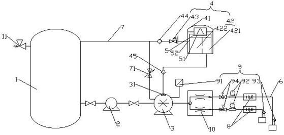
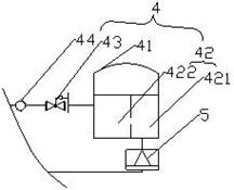
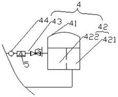
The invention relates to the field of oilfield development, and discloses an injection device for carbon dioxide flooding, which includes a storage tank, a shielded pump, a high-pressure pump and an injection head arranged in sequence, an injection pipeline is arranged between the high-pressure pump and the injection head, and the storage tank and the injection head There is a return line between the high-pressure pumps, and a shut-off valve between the return line and the high-pressure pump. It also includes a gas collection device. The gas collection device includes a gas collection chamber and a pressure regulating device for the outlet of the gas collection chamber. valve, the inlet of the gas collection chamber is connected to the exhaust valve, and the outlet of the pressure regulating device is connected to the storage tank. The present invention for reflux CO 2 The pressure regulation treatment is beneficial to the stability of the storage tank pressure.

Description

technical field [0001] The invention relates to the technical field of oil field development, in particular to an injection device for carbon dioxide flooding. Background technique [0002] In the field of crude oil development, the use of carbon dioxide flooding technology can significantly increase the oil recovery rate for low-permeability reservoirs, and its storage technology can realize the resource utilization of greenhouse gases, which is conducive to environmental protection. [0003] CO 2 The oil displacement surface pressure injection process generally adopts CO 2 Liquid phase CO stored in tanks 2 After being pressurized by the canned pump, it is boosted by the high-pressure pump to reach the injection pressure, and then distributed to the wellhead of the gas injection well. During the operation of the high-pressure pump, the liquid carbon dioxide entering the pump cavity is continuously vaporized, which requires continuous exhaust, which may result in low pump...

Claims


Application Information

Patent Timeline
Patent Type & Authority Patents(China)
IPC IPC(8): E21B43/16
CPCE21B43/164Y02P90/70
Inventor 崔仕章侯云福宋新旺王黎明张凤莲张荣军曾刚高琪琪
Owner DESHI ENERGY TECH GRP CO LTD
Learn More