
Model-based aero-engine performance recovery control method and device

An aero-engine recovery control technology, which is applied in the field of aero-engine performance recovery control and model-based aero-engine performance recovery control, can solve problems such as poor real-time performance, large amount of calculation, and large amount of data, and achieve real-time guarantee of calculation and calculation Efficiency improvement and workload reduction effects

Active Publication Date: 2021-11-12
NANJING UNIV OF AERONAUTICS & ASTRONAUTICS
View PDF6 Cites 3 Cited by
  • Summary
  • Abstract
  • Description
  • Claims
  • Application Information

AI Technical Summary

Problems solved by technology

[0004] However, the solution of the airborne model and the Kalman filter state matrix is ​​the key to realize the model-based engine performance recovery control. At present, the airborne model based on volume dynamics has good real-time performance, but the accuracy is not high and there are few estimable parameters; The airborne model established by the component method has high precision and complete parameters, but the real-time performance is poor; the airborne model established by the piecewise linearization method has good real-time performance, but the model matching error is large and the accuracy is not high
At the same time, the Kalman filter needs to be estimated according to the engine state matrix in real time. The linear Kalman filter is used to obtain the state matrix based on the piecewise linearization model, which has good real-time performance, but the amount of data is large; the extended Kalman filter is calculated in real time. The Jacobian matrix is ​​used to solve the state matrix. The estimation accuracy is high, but the calculation amount is large and the real-time performance is poor.
Therefore, there are still many technical deficiencies in the current model-based engine performance recovery control.

Method used


Image

  • Model-based aero-engine performance recovery control method and device
  • Model-based aero-engine performance recovery control method and device
  • Model-based aero-engine performance recovery control method and device

Examples


Embodiment Construction

[0053] The key to the realization of the model-based engine performance recovery control method lies in the establishment of its on-board adaptive model. The airborne adaptive model is divided into two parts: the airborne model and the Kalman filter to estimate health parameters. At present, there are still many deficiencies in the method. There are few parameters; the airborne model based on the component method has high precision and complete parameters, but the real-time performance is poor; the airborne model established by the piecewise linearization method has good real-time performance, but the model matching error is large and the accuracy is not high. At the same time, the Kalman filter needs to be estimated according to the engine state matrix in real time. The linear Kalman filter is used to obtain the state matrix based on the piecewise linearization model, which has good real-time performance, but the amount of data is large; the extended Kalman filter is used for ...


PUM


Abstract

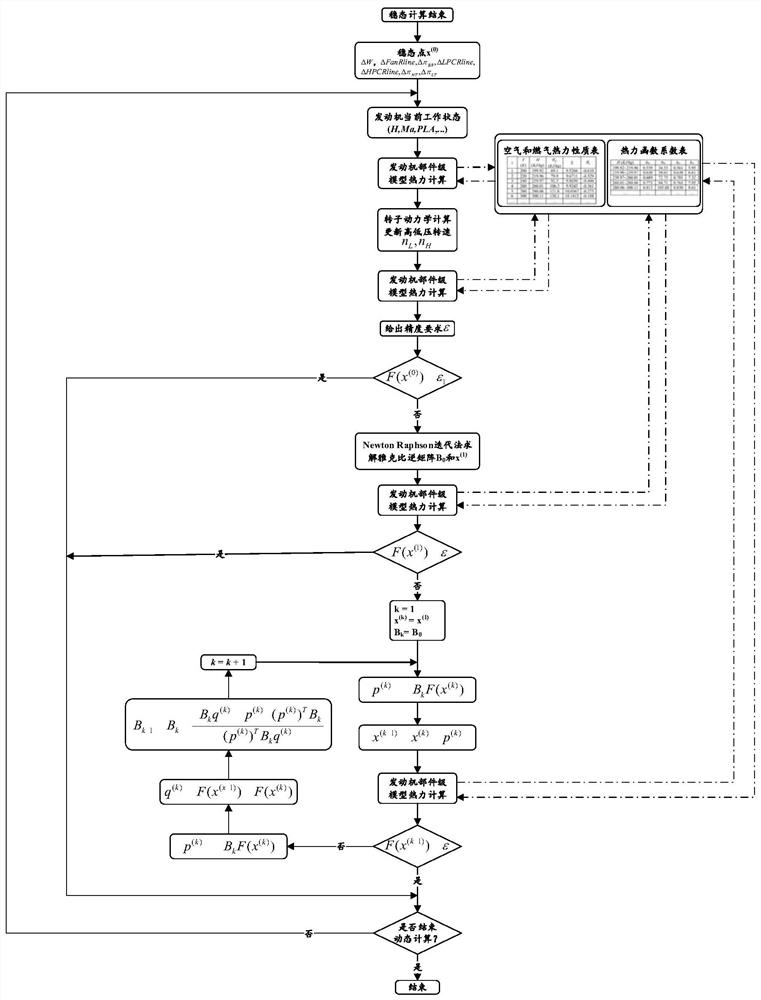
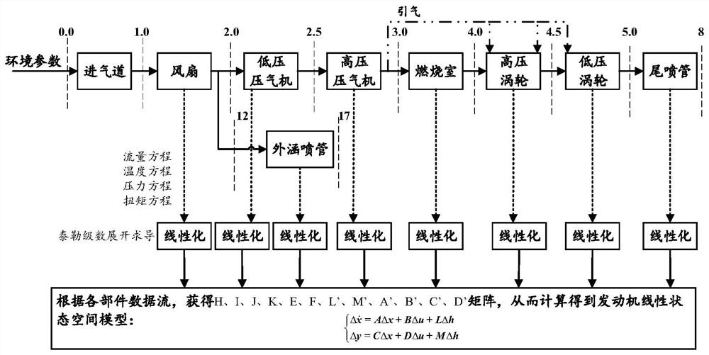
The invention discloses a model-based aero-engine performance recovery control method, and belongs to the technical field of aero-engine control. According to the method, an airborne model is established based on a component method, and real-time optimization is carried out from two aspects of aerodynamic thermal parameter calculation and equilibrium equation iterative solution, so that the calculation amount is greatly reduced; on the basis, in order to further utilize the advantages of simple structure and low calculation complexity of a linear Kalman filter, an airborne model online linearization method is designed so as to update the state matrix in real time and improve the estimation precision of the Kalman filter. The invention further discloses a model-based aero-engine performance recovery control device. Compared with the prior art, the technical scheme of the invention can realize online real-time performance recovery control on the aero-engine.

Description

technical field [0001] The invention relates to an aero-engine performance recovery control method, in particular to a model-based aero-engine performance recovery control method, which belongs to the technical field of aero-engine control. Background technique [0002] During the entire life cycle of an aero-engine, fouling of circulation parts caused by long-term work, increased blade tip clearance of rotating parts, thermal corrosion of high-temperature parts, and creep under high-temperature and high-stress conditions will all cause engine performance degradation, and the results are reflected in the components A reduction in flow capacity and a degradation in efficiency, which will cause deviations between the actual engine and the rated engine of the same type. At this time, if the control system is not adjusted accordingly, it will lead to the loss of engine thrust and other performance. At the same time, because the corresponding relationship between the controlled p...

Claims


Application Information

Patent Timeline
Patent Type & Authority Applications(China)
IPC IPC(8): G06F30/28G06T3/40G06F113/08G06F119/08G06F119/14
CPCG06F30/28G06T3/4007G06F2113/08G06F2119/14G06F2119/08
Inventor 盛汉霖陈芊刘晟奕张晨张杰
Owner NANJING UNIV OF AERONAUTICS & ASTRONAUTICS
Learn More