
Shroud ring linear cutting machining method

A processing method and wire cutting technology, applied in the direction of electric processing equipment, metal processing equipment, metal processing machinery parts, etc., can solve the problems of rough cutting surface, cumbersome processing, and adverse effects on the physical and chemical properties of metal materials, and achieve low processing cost, Fast positioning and less burr effect

Pending Publication Date: 2021-11-16
成都长鼎航空科技有限公司
View PDF0 Cites 0 Cited by
  • Summary
  • Abstract
  • Description
  • Claims
  • Application Information

AI Technical Summary

Problems solved by technology

[0003] In the existing production process of the shroud, it is necessary to cut a series of holes around the shroud. This hole is an irregular hole with a certain angle. The existing processing method is laser cutting, but laser cutting has a cutting surface Roughness, burrs, and high temperature have adverse effects on the physical and chemical properties of the metal material of the shroud, and it is basically impossible to process larger or thicker shrouds. At the same time, in the process of laser cutting, only the The parts lie flat for processing, the laser head needs to move in the horizontal direction and adjust the angle, the processing is more cumbersome

Method used


Image

  • Shroud ring linear cutting machining method
  • Shroud ring linear cutting machining method
  • Shroud ring linear cutting machining method

Examples


Embodiment

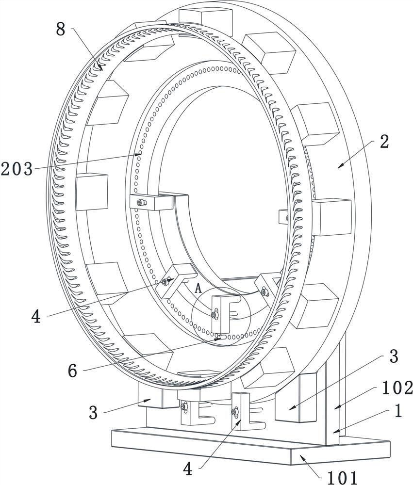
[0041] A kind of shroud line cutting processing method, it is carried out based on shroud processing positioning tooling, and its steps comprise:

[0042] S1, welding the shroud to be processed on the workpiece mounting ring 2 to form the workpiece mounting ring 2 as a whole;

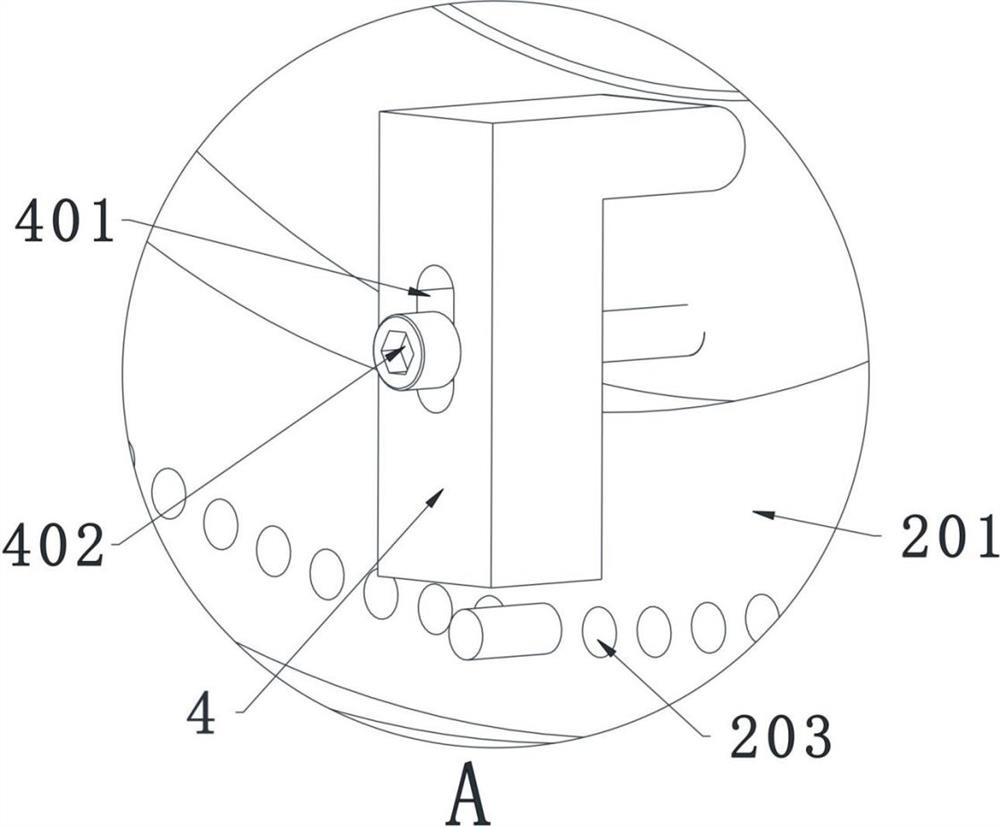
[0043] S2 , drilling the indexing holes 203 and the shroud threading holes on the entire workpiece mounting ring 2 to obtain the whole pre-processed shroud fixed on the workpiece mounting ring 2 .

[0044] S3, cleaning the whole pre-processed shroud and the base 1 installed on the machine tool, and checking the state of the base 1;

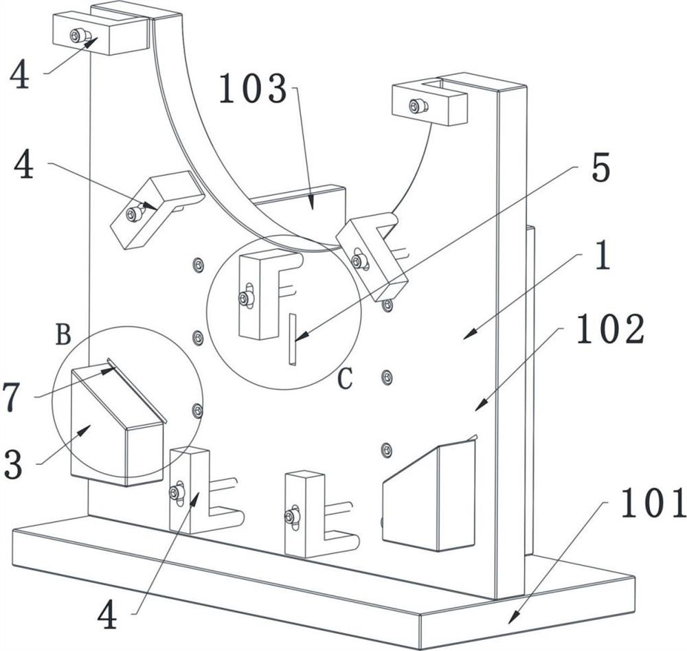
[0045] S4, place the pre-processed shroud as a whole on the receiving block 3, adjust the workpiece mounting ring 2 to make it closely contact with the slopes of the two receiving blocks 3, adjust the angle of the workpiece mounting ring 2 so that any indexing hole 203 is in line with the positioning groove 5 Alignment, and assist and check through positioning pin 6;

[0...


PUM

PropertyMeasurementUnit
Thicknessaaaaaaaaaa

Abstract

The invention discloses a shroud ring linear cutting machining method. The shroud ring linear cutting machining method comprises the following steps that indexing holes are drilled in a workpiece mounting ring; corresponding threading holes are drilled in a to-be-machined shroud ring welded to the workpiece mounting ring; then the whole shroud ring is correctly mounted on a base of a machine tool; detection is conducted; during machining, positioning can be completed by aligning any indexing hole with a positioning groove, positioning can be completed by rotating the angle of the workpiece mounting ring after machining is completed so that the next indexing hole can be aligned with the positioning groove, linear cutting machining of all hole positions can be completed by repeating operation, a tool is adopted for fixing the to-be-machined shroud ring, and a detection gap is formed; and whether the workpiece is installed in place or not can be rapidly judged according to whether a detection card can be inserted or not, rapid positioning of the shroud ring can be guaranteed through the indexing holes in the workpiece mounting ring and other supporting facilities, and vertical linear cutting machining can be conducted through the tool. The shroud ring linear cutting machining method has the advantages of mature processing technology, low cost, few burrs and no influence of high temperature on a material.

Description

technical field [0001] The invention belongs to the technical field of mechanical processing, and in particular relates to a cutting processing method of a girdle line. Background technique [0002] The shroud refers to a structure used in power station steam turbines, gas turbines, aeroengines and other rotating machinery blades to reduce the vibration response of the blades. The shroud structure uses the friction between adjacent blades to dissipate the vibration energy of the blades, so as to achieve the effect of vibration reduction. At the top of the blade, there is an initial gap between the adjacent shrouds of the assembled blades when they are static. During operation, under the action of centrifugal force, the blades are torsionally recovered, making the contact surfaces of adjacent blade shrouds close to each other. When the blades vibrate, The relative slip action between the shroud contact surfaces dissipates the vibration energy of the blade, reduces the vibrat...

Claims


Application Information

Patent Timeline
IPC IPC(8): B23H7/02B23H11/00B23Q17/22
CPCB23H7/02B23H11/003B23Q17/22
Inventor 王刚李彬
Owner 成都长鼎航空科技有限公司
Learn More