Directional oil throwing mechanism for compressor and refrigerator compressor

A compressor and oil throwing technology, which is applied to machines/engines, mechanical equipment, liquid variable volume machinery, etc., can solve problems such as poor lubrication effect, eccentric wear and stuck, piston eccentric wear, etc., to avoid lubricating oil mist. The effect of serious change, ensuring a reasonable height, ensuring stability and reliability

Active Publication Date: 2021-11-16
QINGDAO WANBAO COMPRESSOR
View PDF4 Cites 1 Cited by
  • Summary
  • Abstract
  • Description
  • Claims
  • Application Information

AI Technical Summary

Problems solved by technology

[0003]1. Inclined upward oil groove: When the oil groove compressor with this shape is running, the oil line splash position of the lubricating oil is often higher than the joint between the cylinder hole and the piston at high speed. Insufficient lubrication of the piston is caused. In addition, due to the high oil line, it is easy to throw over the cylinder head to the suction port of the compressor, resulting in too much lubricating oil in the suction system, which affects the performance of the refrigeration system.
[0004]2. Vertical downward oil groove: when the compressor of this shape oil groove is running, the splash position of lubricating oil oil line is relatively low. After the lubricating oil is thrown out, it is directly thrown to the cylinder hole and At the lower end of the piston, the lubricating oil is seriously dispersed and atomized. The atomized lubricating oil is easily sucked into the system, resulting in excessive oil discharge from the compressor, which affects the performance of the refrigeration system. In addition, the splash position of the oil line is too low, and the piston lubrication effect Not good, it is easy to cause partial wear of the piston
[0005]3. Horizontal oil groove or circular oil groove form: this shape oil groove is sealed by the connecting rod, and the lubricating oil is extruded through the eccentric shaft of the crankshaft and the connecting rod along the upper and lower sides, and the oil lines are opposite to each other. It is easy to control, but impurities are easy to accumulate in the eccentric part of the crankshaft, resulting in eccentric wear and sticking, which is not conducive to improving the reliability of the compressor
[0006] Therefore, the existing crankshaft eccentric oil tank mainly relies on the shape of the crankshaft eccentric oil tank to control the splash position of the lubricating oil, and the position and direction of the lubricating oil after being thrown out are difficult to control. Make the lubrication effect is not good, affect the refrigeration system performance of the compressor and the reliability of the compressor

Method used


Image

  • Directional oil throwing mechanism for compressor and refrigerator compressor
  • Directional oil throwing mechanism for compressor and refrigerator compressor
  • Directional oil throwing mechanism for compressor and refrigerator compressor

Examples


Embodiment 1

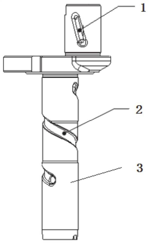
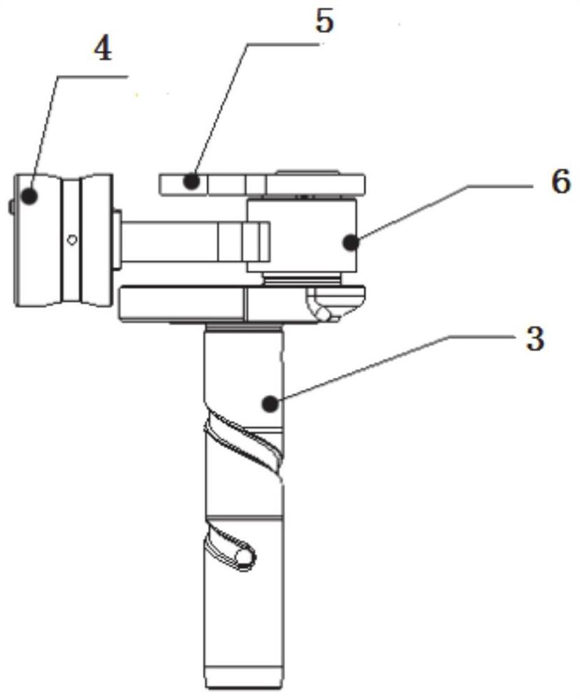
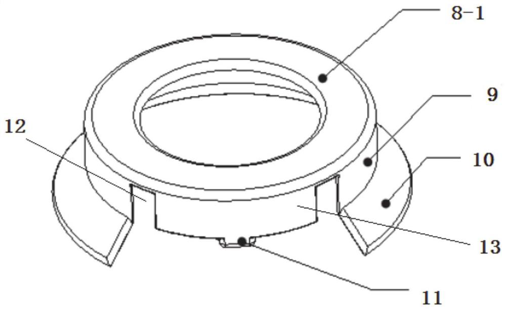
[0041] In a typical embodiment of the present invention, refer to Figure 5-Figure 6 As shown, a directional oil throwing mechanism for a compressor includes a directional cap 14. The directional cap 14 is installed on the side of the crankshaft balance weight opposite to the connecting rod 6, and is arranged opposite to the connecting rod 6. The directional cap 14 is the same as the crankshaft balance weight 5. Matched, the directional cap is connected with the crankshaft balance weight and arranged above the crankshaft balance weight, such as Figure 3-Figure 6 As shown, the side of the directional cap near the crankshaft balance weight 14 has a variable diameter section 10 to control the lubricating oil splash position of the crankshaft oil groove. The ring part 9 of the directional cap is matched with the outer circle of the crankshaft balance weight, and the matching method can be a clearance fit. One end of the ring part is provided with a support, and the support extend...


PUM


Abstract

The invention discloses a directional oil throwing mechanism for a compressor and a refrigerator compressor. The directional oil throwing mechanism comprises a directional cap, wherein the directional cap is mounted at one side, opposite to a connecting rod, of a crankshaft balance block, the directional cap is matched with the crankshaft balance block, the directional cap is connected with the crankshaft balance block, and one side, close to the crankshaft balance block, of the directional cap is provided with a reducing section to control the lubricating oil splashing position of a crankshaft oil groove. the oil line splashing position of lubricating oil can be effectively controlled by adjusting the length and slope of the horn mouth of the directional cap according to the requirements of compressors of different sizes for the oil line splashing position, the amount of lubricating oil sucked into the system is reduced while a piston is fully lubricated, and the product reliability and the overall performance of a refrigerating system are improved.

Description

technical field [0001] The invention relates to the technical field of refrigerator compressors, in particular to a directional oil throwing mechanism for a compressor and a refrigerator compressor. Background technique [0002] The reciprocating piston compressor for refrigerator refrigeration is mainly based on the crank-link mechanism, including the crankshaft, connecting rod, piston pin, piston and cylinder seat. Cooperating with the piston, the crankshaft rotates to make the piston reciprocate in the cylinder hole of the cylinder block. The crankshaft main shaft and the outer circle of the eccentric part have oil groove channels for lubricating oil to pass through. When the compressor is running, the lubricating oil passes through the bottom of the compressor housing The crankshaft main shaft oil tank enters the eccentric oil tank, and is finally thrown out under the action of centrifugal force and splashed to the joint between the cylinder hole and the piston to realiz...

Claims


Application Information

Patent Timeline
Patent Type & Authority Applications(China)
IPC IPC(8): F04B39/02
CPCF04B39/0284F04B39/0276Y02B40/00
Inventor 朱鲁栋邓安义周凯旋曲馨常伟毛成林徐廉洲
Owner QINGDAO WANBAO COMPRESSOR
Why Eureka
Try Eureka