

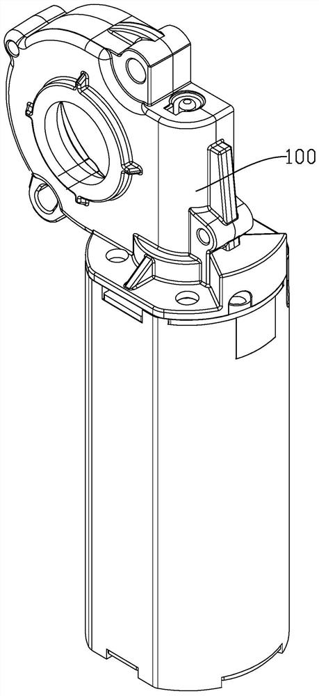
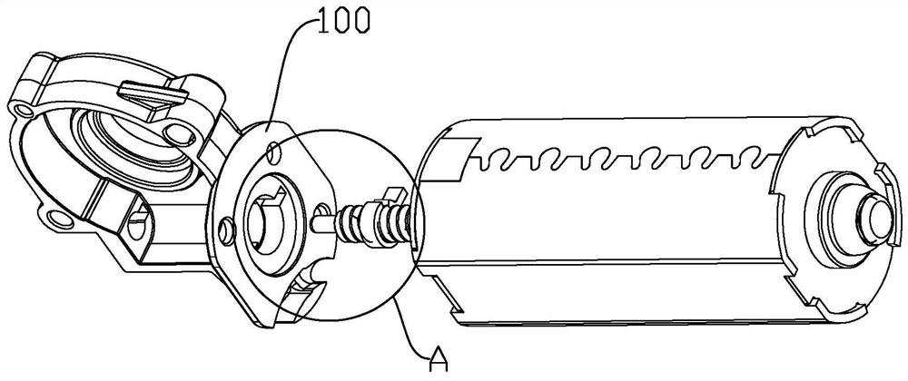
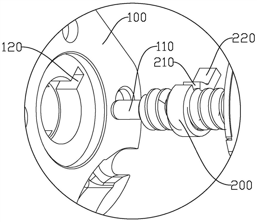
Self-locking device suitable for motor and linear actuator
A linear actuator and self-locking device technology, applied in the field of motors, can solve problems affecting equipment stability, noise, and inconvenient installation
- Summary
- Abstract
- Description
- Claims
- Application Information
AI Technical Summary
Problems solved by technology
Method used
Image

Examples
Embodiment Construction
[0061] The technical scheme of the embodiment of the present invention will be explained and explained in connection with the accompanying drawings of the embodiments of the present invention, but the following examples are merely preferred embodiments of the present invention, not all. Based on the embodiments in the embodiment, those skilled in the art will belong to the scope of the present invention without making creative labor.
[0062] In the description of the present invention, it is to be understood that the term "center", "longitudinal", "lateral", "length", "width", "thickness", "upper", "lower", "front", " orientation or positional relationship rear "," left "," right "," vertical "," horizontal "," top "," bottom "," inner "," clockwise "," counterclockwise "and the like based on the attachment indicated by FIG positional relationship or orientation, for convenience of description only and the present invention is to simplify the description, but does not indicate or...
PUM
 Abstract
Description
Claims
Application Information