Eureka AIR delivers breakthrough ideas for toughest innovation challenges, trusted by R&D personnel around the world.

Tubular furnace emergency cut-off valve device with detection mechanism and method

A detection mechanism and valve device technology, applied in the direction of valve device, measuring device, furnace control device, etc., can solve the problems of cracking, flange flying out, unfavorable application and operation, lack of detection mechanism, etc., and achieve compact structure and practicality Strong, simple and convenient operation

Pending Publication Date: 2021-11-16
内江市博威能源有限公司
View PDF0 Cites 0 Cited by
  • Summary
  • Abstract
  • Description
  • Claims
  • Application Information

AI Technical Summary

Problems solved by technology

[0003] In the prior art, when the tube furnace is in use, if it is necessary to close the exhaust valve and the inlet valve to heat the sample in the experiment of heating the sample, the operator needs to pay attention to the indication of the pressure gauge at all times. When it is greater than the set value, the intake air must be cut off immediately to prevent accidents such as furnace tube rupture and flange flying out. However, due to the lack of detection mechanism for the tube furnace cut-off valve in the prior art, in actual The above operations are required during the operation of the system. Such operations not only require the operator to always pay attention to the indications of the pressure gauge, but also require the operator to manually control the shut-off valve for emergency cut-off operation. If the cut-off is not timely, it will cause certain accidents. Occurs, which is not conducive to the actual application and operation

Method used


Image

  • Tubular furnace emergency cut-off valve device with detection mechanism and method
  • Tubular furnace emergency cut-off valve device with detection mechanism and method
  • Tubular furnace emergency cut-off valve device with detection mechanism and method

Examples


Embodiment

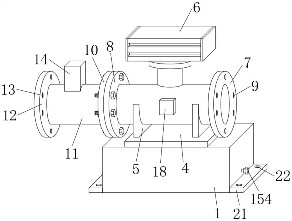
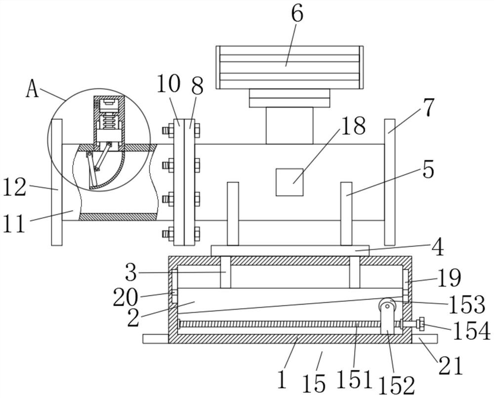
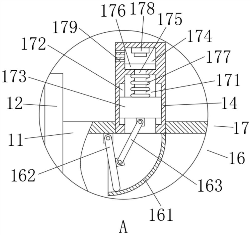
[0027] A tube furnace emergency cut-off valve device with a detection mechanism, comprising an installation box 1, a trapezoidal block 2 is slidably connected to the inside of the installation box 1, and a trapezoidal block 2 is provided inside the installation box 1 and below the trapezoidal block 2. Height adjustment mechanism 15, both ends of the top of the trapezoidal block 2 are fixedly connected with support rods 3, the tops of the support rods 3 all extend to the top of the installation box 1, and the tops of the two support rods 3 are fixed between A fixing plate 4 is connected, and the fixing plate 4 can be better installed on the top of the trapezoidal block 2 through the support rod 3; both ends of the top of the fixing plate 4 are fixedly connected with a vertical plate 5. A shut-off valve 6 is fixedly connected between the tops of the plates 5, and the shut-off valve 6 can be better installed and fixed through the vertical plate 5; the output end of the shut-off va...


PUM


Abstract

The invention discloses a tubular furnace emergency cut-off valve device with a detection mechanism and a method. The tubular furnace emergency cut-off valve device comprises a mounting box, a trapezoidal block is slidably connected to the interior of the mounting box, a height adjusting mechanism is arranged in the mounting box and located below the trapezoidal block, supporting rods are fixedly connected to the two ends of the top of the trapezoidal block, the tops of the supporting rods are extended to the top of the mounting box, and a fixing plate is fixedly connected between the top of the two supporting rods, the tubular furnace emergency cut-off valve is compact in structure, easy and convenient to operate and high in practicability, the pressure of airflow in a pipeline can be detected in real time by arranging a detection pipe with the detection mechanism on one side of a traditional cut-off valve, meanwhile, a buffer mechanism is matched, emergency cut-off operation can be conducted in time when the pressure of the airflow in the pipeline exceeds the standard, manual real-time observation of the numerical value of a pressure gauge is not needed, manual emergency cut-off operation is not needed either, potential safety hazards of equipment are greatly reduced, and actual application and operation are facilitated.

Description

technical field [0001] The invention belongs to the field of cut-off valves, in particular to a tubular furnace emergency cut-off valve device and method with a detection mechanism. Background technique [0002] In the current life, tube furnaces are mainly used in metallurgy, glass, heat treatment, lithium battery anode and cathode materials, new energy, abrasive tools and other industries. It is a professional equipment for measuring materials under certain temperature conditions. The furnace structure is simple and easy to operate. It is easy to control and can be continuously produced, and the shut-off valve is a kind of actuator in the automation system. It is composed of a multi-spring pneumatic film actuator or a floating piston actuator and a regulating valve. The shut-off valve has a wide range of uses and can be used to cut off gas, Combustion-supporting air, cold air and flue gas, etc., are often provided with cut-off valves inside the tube furnace to control the ...

Claims


Application Information

Patent Timeline
Patent Type & Authority Applications(China)
IPC IPC(8): F16K17/00F16K27/00F16K31/02F16K37/00F17D5/00G01L11/00F27B17/02F27D19/00
CPCF16K17/00F16K31/02F16K37/005F16K27/00F17D5/005G01L11/00F27B17/02F27D19/00F27D2019/0006F27D2019/0028
Inventor 王国能彭望吴惑孔祥凤胡旗显向前勇倪乾刚
Owner 内江市博威能源有限公司
Why Eureka
Eureka Blog
Learn More