
Clamp and method for dynamic test of IGBT device

A dynamic test and fixture technology, applied in the field of IGBT devices, can solve the problems of heavy workload, complex operation, and large stray inductance of the test circuit, and achieve the effect of improving reliability and reducing stray inductance

Pending Publication Date: 2021-11-16
ZHUZHOU CRRC TIMES SEMICON CO LTD
View PDF0 Cites 2 Cited by
  • Summary
  • Abstract
  • Description
  • Claims
  • Application Information

AI Technical Summary

Problems solved by technology

This method does not carry out low-inductance design, so the stray inductance in the test circuit is large; and every measurement needs to repeatedly disassemble the connecting wire between the capacitor and the electrode of the component under test, the workload is heavy and the operation is complicated

Method used


Image

  • Clamp and method for dynamic test of IGBT device
  • Clamp and method for dynamic test of IGBT device
  • Clamp and method for dynamic test of IGBT device

Examples


Embodiment Construction

[0049] The present invention will be further described below in conjunction with accompanying drawing.

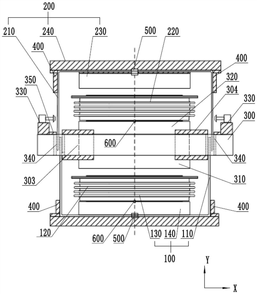
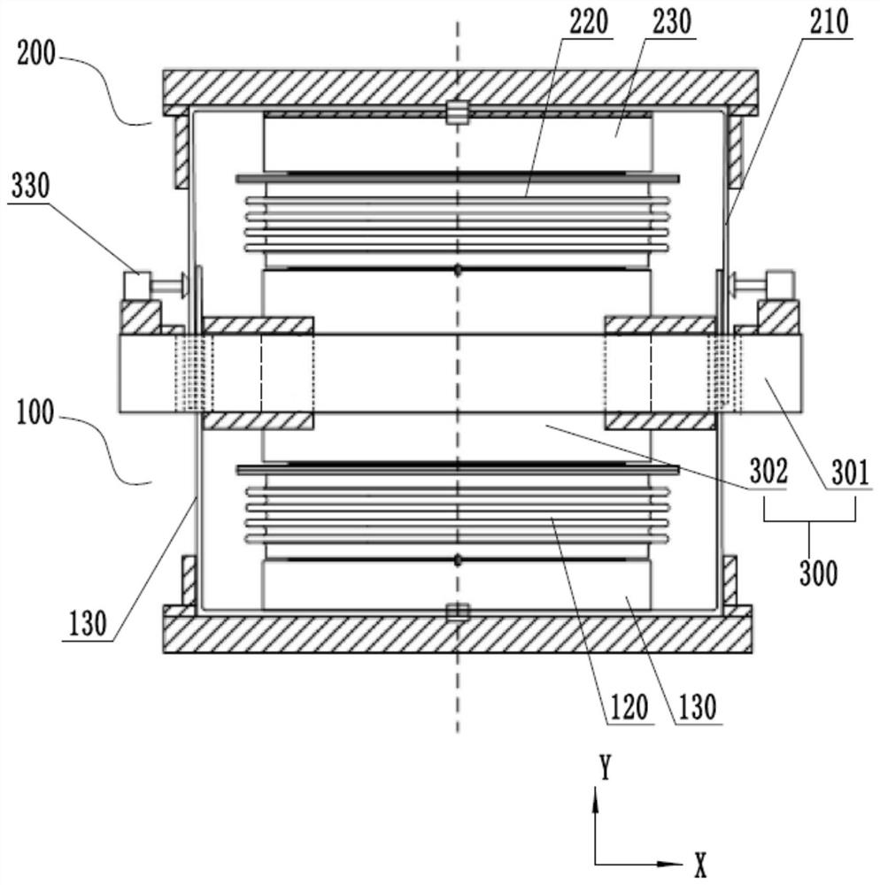
[0050] Such as figure 1 and 2 As shown, according to the first aspect of the present invention, the present invention provides a fixture for dynamic testing of IGBT devices, which includes a first fixture 100 , a second fixture 200 and a support frame 300 . Wherein, the first clamp 100 is used to clamp the first IGBT device 120, the second clamp 200 is used to clamp the second IGBT device 220, the support frame 300 is arranged between the first IGBT device 120 and the second IGBT device 220, the second The first clamp 100 and the second clamp 200 are respectively located on two sides of the support frame 300 , and are approximately symmetrically arranged with the support frame 300 as a symmetry axis.

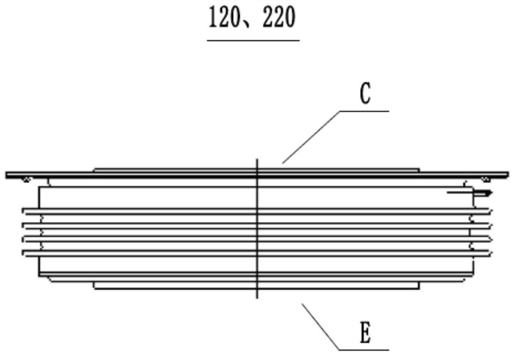
[0051] Such as image 3 As shown, the first IGBT device 120 and the second IGBT device 220 are pressure-connected IGBT devices as an example for description. Both are fla...


PUM


Abstract

The invention relates to a clamp and a method for dynamic test of an IGBT device, relates to the technical field of IGBT devices, and is used for reducing stray inductance in a test circuit. The clamp for dynamic testing of the IGBT devices comprises a first clamp, a second clamp and a supporting frame, the first clamp and the second clamp are arranged to be symmetrical about the first IGBT device and the second IGBT device respectively and are of a stacked structure, and therefore stray inductance in a test circuit is reduced by means of the electromagnetic coupling principle, and the reliability of the dynamic parameter test of the device can be improved.

Description

technical field [0001] The invention relates to the technical field of IGBT devices, in particular to a fixture and method for dynamic testing of IGBT devices. Background technique [0002] IGBT dynamic testing is an important technical means to understand the real performance of the device under specific application conditions. By building a half-bridge circuit for testing, the switching process parameters of the IGBT device are obtained to confirm the selection of the dead time of the driving signal and the calculation of the loss, and evaluate Whether the driving parameters are selected is reasonable, and at the same time obtain the anti-parallel diode characteristics of the internal package of the device, including diode reverse recovery current, reverse safe operating area (RRSOA) and turn-off waveform, etc., to evaluate whether it meets the requirements. [0003] In the actual application of IGBT devices, the parasitic stray inductance of the connection line has a sign...

Claims


Application Information

Patent Timeline
IPC IPC(8): G01R1/04G01R31/26
CPCG01R1/0416G01R31/2601
Inventor 王真万超群李贵生陈彦宋自珍陈喻李义翟龙朱婷
Owner ZHUZHOU CRRC TIMES SEMICON CO LTD
Features
  • Generate Ideas
  • Intellectual Property
  • Life Sciences
  • Materials
  • Tech Scout
  • Unparalleled Data Quality
  • Higher Quality Content
  • 60% Fewer Hallucinations
Learn More