Follow-up delivery actuator and auricle clip delivery device
An actuator and follow-up technology, applied in the field of medical devices, can solve the problems of inconvenient operation and large volume, and achieve the effect of convenient omnidirectional orientation effect.
- Summary
- Abstract
- Description
- Claims
- Application Information
AI Technical Summary
Problems solved by technology
Method used
Image
Examples
Embodiment 1
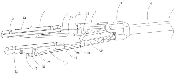
[0046] figure 1 It is a schematic diagram showing the first perspective stereoscopic structure of the conveying device in Embodiment 1 of the present invention, figure 2 It is a schematic diagram showing the stereoscopic structure of the second viewing angle of the conveying device in Embodiment 1 of the present invention, and image 3 It is a schematic diagram showing the structure of the conveying actuator in Embodiment 1 of the present invention; Embodiment 1 of the present application provides a follow-up conveying actuator, which mainly includes a first tong arm 1, a second tong arm 2, a connecting rod 3, and a joint 4 and two connecting arms 5. The first pliers arm 1 and the second pliers arm 2 forming the jaws are hinged at the front end of the joint 4 in an openable and closable manner, and the connecting rod 3 can be hinged at the root of the jaws to the first jaw. Between the arm 1 and the second pliers arm 2, the connecting rod 3 can be used to controllably open ...
Embodiment 2
[0059] Figure 6 It is a schematic diagram showing the three-dimensional structure of the conveying device in Embodiment 2 of the present invention, Figure 7 It is a structural schematic diagram showing the first viewing angle of the coupling of the conveying device in Embodiment 2 of the present invention, and Figure 8It is a schematic structural diagram showing the second viewing angle of the shaft coupling of the conveying device in the second embodiment of the present invention.
[0060] As shown in the figure, the main difference between the second embodiment of the present application and the first embodiment is that in this embodiment, an omnidirectional joint is used to carry out the free orientation of the actuator, wherein the joint 4 includes a pivot seat 43, a coupling 42 and the interface 41 connected with the connecting rod 6, the pivot seat 43 includes a first pivot seat 433 and a second pivot seat 435, and a connecting shaft can be fixed through the first sh...
Embodiment 3
[0065] Figure 9 It is a schematic structural diagram showing the delivery actuator in Embodiment 3 of the present invention, and Figure 10 It is a schematic structural diagram showing the delivery device in Embodiment 3 of the present invention. As shown in the figure, the main difference between Embodiment 2 of the present application and Embodiment 1 and 2 is that in this embodiment, a set of disc spring joints 61 (or called ball hinge joints) arranged on the connecting rod 6 are used to Carry out the free orientation of actuator, simultaneously by the shape of controller 8 given in this embodiment, can understand a kind of controller shape that can be applied in the actuator of other embodiments of the present application, wherein controller 8 can be a gun grip Bundle. A wrench 81 can be hinged at the front end, and the wrench 81 can be used to connect with the connecting rod 3 through a control line, so as to control the opening or closing of the actuator.
[0066] Wh...
PUM
 Abstract
Description
Claims
Application Information
 - R&D
- Intellectual Property
- Life Sciences
- Materials
- Tech Scout
- Unparalleled Data Quality
- Higher Quality Content
- 60% Fewer Hallucinations
Browse by: Latest US Patents, China's latest patents, Technical Efficacy Thesaurus, Application Domain, Technology Topic, Popular Technical Reports.
© 2025 PatSnap. All rights reserved.Legal|Privacy policy|Modern Slavery Act Transparency Statement|Sitemap|About US| Contact US: help@patsnap.com


