Bottle cap high-speed removing device based on gas distribution disc

A technology of rejecting device and gas distribution plate, which is applied in the direction of sorting, etc., can solve the problems of unqualified caps mixed into the finished cap area, increase the transmission structure, and imprecise rejecting positions, so as to achieve easy maintenance and operation, easy system construction, and adsorption Stable and reliable effect

Pending Publication Date: 2021-11-19
FOSHAN DING ZHONG MACHINERY
View PDF11 Cites 0 Cited by
  • Summary
  • Abstract
  • Description
  • Claims
  • Application Information

AI Technical Summary

Problems solved by technology

The original method of rejecting metal bottle cap production has the characteristics of simple electrical control, and the visual inspection device and rejecting device are not easy to install, but it also brings many disadvantages:
[0003] 1. The removal speed is slow;
[0004] 2. The removal position is inaccurate, which may easily cause unqualified caps to be mixed into the finished cap area;
[0005] 3. Increase the transmission structure and increase the negative pressure load, resulting in an increase in manufacturing costs;
[0006] 4. The speed of the transmission mechanism and the output disc of the lamination molding machine is docked, which causes the gap between the caps to be different, and also causes the metal bottle cap to deflect at a certain angle, which increases the difficulty of detection and removal by the 3D visual inspection system

Method used


Image

  • Bottle cap high-speed removing device based on gas distribution disc
  • Bottle cap high-speed removing device based on gas distribution disc
  • Bottle cap high-speed removing device based on gas distribution disc

Examples


Embodiment Construction

[0018] The following will clearly and completely describe the technical solutions in the embodiments of the present invention with reference to the accompanying drawings in the embodiments of the present invention. Obviously, the described embodiments are only some, not all, embodiments of the present invention. Based on the embodiments of the present invention, all other embodiments obtained by persons of ordinary skill in the art without making creative efforts belong to the protection scope of the present invention.

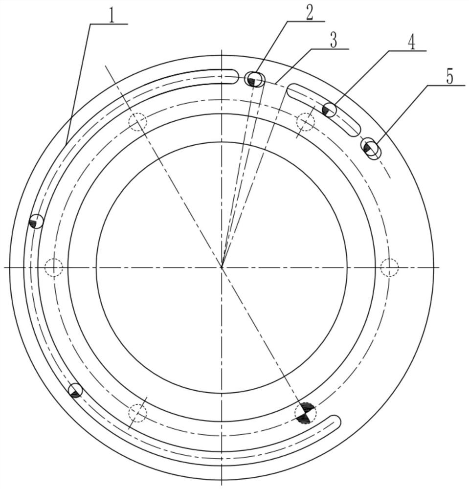
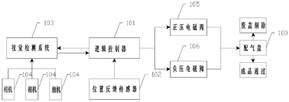
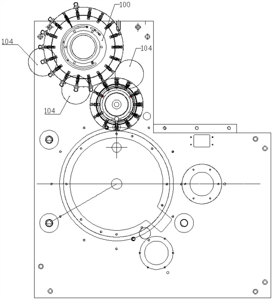
[0019] see Figure 1-3 , the present invention provides a technical solution: a bottle cap rejecting device based on a gas distribution plate, including: the embodiment in the present invention, all other implementations obtained by those of ordinary skill in the art without creative work For example, all belong to the protection scope of the present invention.

[0020] see Figure 1-3 , the present invention provides a technical solution: a bottle cap rejec...


PUM


Abstract

The invention discloses a bottle cap high-speed removing device based on a gas distribution disc. The device comprises a visual detection system, a logic controller and the gas distribution disc, the visual detection system is used for detecting whether bottle caps meet the standard or not, the logic controller is used for controlling operation of the gas distribution disc, a plurality of gas guide grooves are formed in the gas distribution disc, and suction cups are arranged on the gas guide grooves; the plurality of gas guide grooves are divided into a first negative pressure normally-open area, a positive and negative pressure interaction area, a pressure breaking area, a second negative pressure normally-open area and a positive pressure normally-open area, and negative pressure is introduced into the first negative pressure normally-open area and the second negative pressure normally-open area to be used for adsorbing bottle caps; positive pressure is introduced into the positive pressure normally-open area to be used for blowing off the bottle caps; positive pressure or negative pressure can be introduced into the positive and negative pressure interaction area to be used for screening the bottle caps; and the pressure breaking area is used for balancing positive pressure when the bottle caps are blown off in the positive pressure normally-open area. The device is simple in structure and high in removing speed, the whole structure of the gas distribution disc is easy to install, the bottle caps are sucked stably and reliably, meanwhile, maintenance and operation are convenient, a system is easy to build, cost is low, and the device is suitable for popularization.

Description

technical field [0001] The invention relates to the technical field of packaging equipment, in particular to a high-speed bottle cap removal device based on a gas distribution plate. Background technique [0002] The current production process of metal bottle caps in the packaging industry is mainly composed of stamping, molding, glue molding, visual inspection, and waste rejection; Nozzles are used for the removal, and the cylinder removal method is used. Although the removal position is accurate, the shortest time for the cylinder to extend and retract the entire stroke on the market is about 40ms, which cannot meet the requirements of high-speed production. However, with the blowing nozzle blowing method, although the response speed is fast, a high positive pressure air flow is required to meet the high-speed removal efficiency. And if the gas flow rate is too large, it may affect the position deviation of the latter cover, resulting in inaccurate rejection. The high-sp...

Claims


Application Information

Patent Timeline
Patent Type & Authority Applications(China)
IPC IPC(8): B07C5/36B07C5/34
CPCB07C5/362B07C5/34
Inventor 于超发李朋胡阔江
Owner FOSHAN DING ZHONG MACHINERY
Why Eureka
Try Eureka