
Hob machine for communication electronic material machining

A technology of electronic materials and hobs, which is applied in the direction of metal processing machinery parts, metal processing equipment, manufacturing tools, etc., can solve problems such as damage to hobs and processing rollers, failure to adjust, damage to electronic materials, etc., to avoid excessive temperature, Avoid the effect of increasing the defective rate

Active Publication Date: 2021-11-19
徐州和润电子材料有限公司
View PDF9 Cites 3 Cited by
  • Summary
  • Abstract
  • Description
  • Claims
  • Application Information

AI Technical Summary

Problems solved by technology

[0003] During the use of the existing hob machine for processing electronic materials for communication, it is impossible to adjust the tension of the electronic material according to the thickness and performance of the electronic material, which is easy to damage the electronic material, and lacks the cooling of the hob and processing roller During processing, the surface temperature of hobs and processing rollers will rise rapidly due to friction, which will easily damage the hobs and processing rollers and reduce the service life of hobs and processing rollers. In addition, electronic materials will generate a large amount of These debris and dust will fall on the surface of electronic materials, and the existing hobs for processing electronic materials for communication lack cleaning devices, resulting in debris and dust remaining on the surface of electronic materials, making it difficult to proceed to the next step processing

Method used


Image

  • Hob machine for communication electronic material machining
  • Hob machine for communication electronic material machining
  • Hob machine for communication electronic material machining

Examples


Embodiment 1

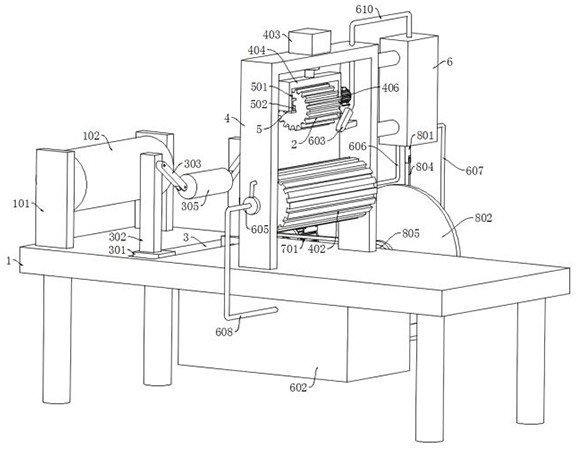
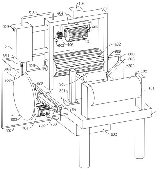
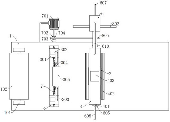
[0030] refer to Figure 1-Figure 5 , Figure 12, a hob machine for processing electronic materials for communication, comprising a workbench 1 and a hob 2, two fixed plates 101 are symmetrically fixedly connected to the upper end of the workbench 1, and the side walls of the two fixed plates 101 are connected to each other by rotation and are wound Roller 102, the electronic material can be installed on the winding roller 102, an adjustment mechanism is installed on the workbench 1, the adjustment mechanism includes a chute 3 set on the upper end of the workbench 1, the inner wall of the chute 3 is symmetrically slidably connected with two sliders 301, The upper ends of the two sliders 301 are fixedly connected with two vertical rods 302, the side walls of the two vertical rods 302 are rotatably connected with two connecting rods 303, and the other ends of the two connecting rods 303 are jointly rotatably connected with a rotating rod 304, and the sides of the rotating rod 304...

Embodiment 2

[0040] refer to Figure 6-Figure 7 The difference between this embodiment and Embodiment 1 is that a cleaning mechanism is installed on the workbench 1, and the cleaning mechanism includes two vertical plates 9 symmetrically fixedly connected to the upper end of the workbench 1, and the side walls of the two vertical plates 9 are close to each other to rotate Two fourth rotating shafts 901 are connected, and the side walls of the two fourth rotating shafts 901 close to each other are jointly rotated and connected with a cleaning roller 902. The side walls of the cleaning roller 902 are fixedly connected with a plurality of bristles, and one end of the fourth rotating shaft 901 runs through the vertical plate 9 side walls are fixedly connected with a second driven wheel 903, and the driving wheel 704, the first driven wheel 805 and the second driven wheel 903 are connected by a synchronous belt.

[0041] In this embodiment, when the second motor 701 reversely rotates to drive t...

Embodiment 3

[0043] refer to Figure 7-Figure 11 The difference between this embodiment and Embodiment 2 is that: a dust suction mechanism is installed on the workbench 1, and the dust suction mechanism includes a dust collection box 10 fixedly connected to the lower end of the workbench 1, and the side wall of the dust collection box 10 is symmetrically provided with two Air vent, the cleaning roller 902 is provided with a dust suction chamber 1001, the side wall of the dust suction chamber 1001 is provided with a plurality of dust suction holes 1002, and the side wall of the other fourth rotating shaft 901 is provided with a vertical slot 1003, and the dust suction chamber 1001 passes through the hole slots 1004 is in communication with the vertical groove 1003, and the side wall of the other vertical plate 9 is fixedly connected with the second rotary joint 1005 through the bracket, and one end of the other fourth rotating shaft 901 passes through the side wall of the vertical plate 9 an...


PUM


Abstract

The invention discloses a hob machine for communication electronic material machining. The hob machine for communication electronic material machining comprises a workbench and a hob, wherein two fixing plates are symmetrically and fixedly connected to the upper end of the workbench, the side walls, close to each other, of the two fixing plates are jointly and rotationally connected with a winding roller, and an adjusting mechanism is installed on the workbench. The adjusting mechanism comprises a sliding groove formed in the upper end of the workbench, two sliding blocks are symmetrically connected to the inner wall of the sliding groove in a sliding mode, two vertical rods are fixedly connected to the upper ends of the two sliding blocks, two connecting rods are rotationally connected to the side walls of the two vertical rods, and a rotating rod is jointly and rotationally connected to the other ends of the two connecting rods, and the side wall of the rotating rod is rotationally connected with an adjusting roller. According to the hob machine for communication electronic material machining, a second motor is driven to rotate in the forward direction to drive the adjusting roller to move, and then the electronic materials are pressed or loosened; and in this way, the tightening degrees of different electronic materials are conveniently adjusted, and the situation that the defective rate of machining is increased due to the fact that the electronic materials are too tight or too loose in the machining process is avoided.

Description

technical field [0001] The invention relates to the technical field of communication electronic material processing, in particular to a hob machine for communication electronic material processing. Background technique [0002] Electronic materials refer to materials used in electronic technology, including semiconductor materials, dielectric materials, etc. Electronic materials are currently the material basis of the industrial field, and the actual production and processing processes are relatively complicated. [0003] During the use of the existing hob machine for processing electronic materials for communication, it is impossible to adjust the tension of the electronic material according to the thickness and performance of the electronic material, which is easy to damage the electronic material, and lacks the cooling of the hob and processing roller During the processing of the device, the hob and processing roller, the temperature of the friction surface will rise rapi...

Claims


Application Information

Patent Timeline
Patent Type & Authority Applications(China)
IPC IPC(8): B23D79/00B23Q3/06B23Q11/00B23Q11/10
CPCB23D79/00B23Q3/062B23Q11/10B23Q11/005B23Q11/0067
Inventor 徐建萍
Owner 徐州和润电子材料有限公司
Learn More