
Heat supply structure for air compressor

A technology of air compressors and air compressor units, applied in mechanical equipment, machines/engines, liquid variable capacity machines, etc., can solve the problems of less available space, waste of energy, waste of heat, etc., to save fuel and energy, Ease of use and saving a lot of resources

Inactive Publication Date: 2021-11-19
衣轶欧
View PDF0 Cites 0 Cited by
  • Summary
  • Abstract
  • Description
  • Claims
  • Application Information

AI Technical Summary

Problems solved by technology

[0003] However, when the air compressor works for a long time, it will inevitably generate high heat. Generally, heat is exchanged through static heat dissipation, such as heat dissipation fins, and water cooling and air cooling. However, the heat dissipation mechanism is easily overloaded and the use of heat is not perfect. , leading to heat loss and waste of energy. The power of the marine air compressor is relatively large, generally in the form of a unit, and the heat generated can even reach more than 180 degrees Celsius. However, due to the less available space of the ship and the heat recovery equipment The installation is limited. Ships usually use seawater to cool down and dissipate heat, which leads to waste of heat. This method also causes disadvantages such as accelerated corrosion of pipelines.

Method used


Image

  • Heat supply structure for air compressor
  • Heat supply structure for air compressor

Examples


Embodiment Construction

[0024] The following will clearly and completely describe the technical solutions in the embodiments of the present invention with reference to the accompanying drawings in the embodiments of the present invention. Obviously, the described embodiments are only some, not all, embodiments of the present invention. Based on the embodiments of the present invention, all other embodiments obtained by persons of ordinary skill in the art without making creative efforts belong to the protection scope of the present invention.

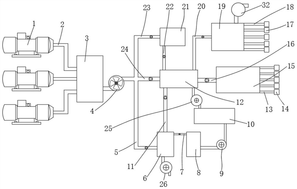
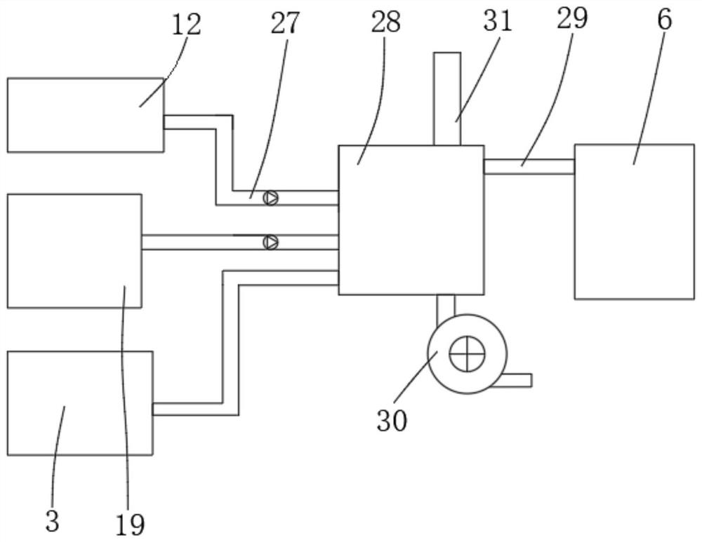
[0025] see figure 1 , the present invention provides a technical solution: a heat supply structure for an air compressor, comprising multiple sets of air compressor units 1 and a gas pipeline-2 connected to the heat output end of the air compressor set 1, and multiple sets of air compressor units The heat output ends of group 1 are all connected to the heat storage tank 3 through the gas transmission pipeline 12, and the inside of the heat storage tank 3 is us...


PUM


Abstract

The invention discloses a heat supply structure for an air compressor. The heat supply structure comprises a plurality of air compressor units and a first gas pipeline communicating with the heat output ends of the air compressor units, the heat output ends of the multiple air compressor units communicate with a heat storage tank through the first gas pipeline, and the interior of the heat storage tank is used for storing high-temperature gas. The output end of the heat storage tank communicates with a heat utilization distillation mechanism, the heat utilization distillation mechanism comprises a second gas pipeline, the second gas pipeline communicates with the output end of a centrifugal fan, the output end of the second gas pipeline communicates with a distillation chamber, and the inner wall of the second gas pipeline is provided with a one-way valve which flows into the distillation chamber in a one-way mode. The input end of the distillation chamber communicates with a third water pump, and the third water pump is used for supplementing quantitative seawater. Through cooperation of the structures, heat generated by the compressor is utilized in a multi-stage gradient mode, heat emission is reduced, and fuel energy is saved.

Description

technical field [0001] The invention relates to the technical field of marine air compressors, in particular to a heating structure for air compressors. Background technique [0002] Air compressors are used in a wide range of fields, including compressed air to provide power, such as pneumatic sandblasting, pneumatic wrenches and jacks, as well as automatic control, food, pharmaceutical and marine diesel drives, etc., and air compressors are especially used on ships. Widely used, it can be used for refrigeration by compressing refrigerant liquid, and it can also be used to assist ship starting by compressing air. [0003] However, when the air compressor works for a long time, it will inevitably generate high heat. Generally, heat is exchanged through static heat dissipation, such as heat dissipation fins, and water cooling and air cooling. However, the heat dissipation mechanism is easily overloaded and the use of heat is not perfect. , leading to heat loss and waste of e...

Claims


Application Information

Patent Timeline
Patent Type & Authority Applications(China)
IPC IPC(8): F04B37/12F04B39/00F04B39/06F04B39/12
CPCF04B37/12F04B39/123F04B39/064F04B39/12F04B39/00
Inventor 衣轶欧严新乔易江
Owner 衣轶欧
Learn More