On-orbit optimization method for key calibration parameters of infrared hyperspectral interferometer

An optimization method and hyperspectral technology, applied in the field of infrared interferometer, can solve problems such as errors, inability to directly obtain calibration parameters, and high cost of laboratory calibration parameters

Pending Publication Date: 2021-11-19
NAT SATELLITE METEOROLOGICAL CENT
View PDF0 Cites 0 Cited by
  • Summary
  • Abstract
  • Description
  • Claims
  • Application Information

AI Technical Summary

Problems solved by technology

[0003] In the existing technology, due to the difference between the on-orbit state of the instrument and the vacuum state in the laboratory, when the laboratory calibration parameters are used for on-orbit data calibration, errors may be caused, and the acquisition of laboratory calibration parameters is expensive. Calibration parameters cannot be obtained directly after the instrument is in orbit

Method used


Image

  • On-orbit optimization method for key calibration parameters of infrared hyperspectral interferometer
  • On-orbit optimization method for key calibration parameters of infrared hyperspectral interferometer
  • On-orbit optimization method for key calibration parameters of infrared hyperspectral interferometer

Examples


Embodiment 1

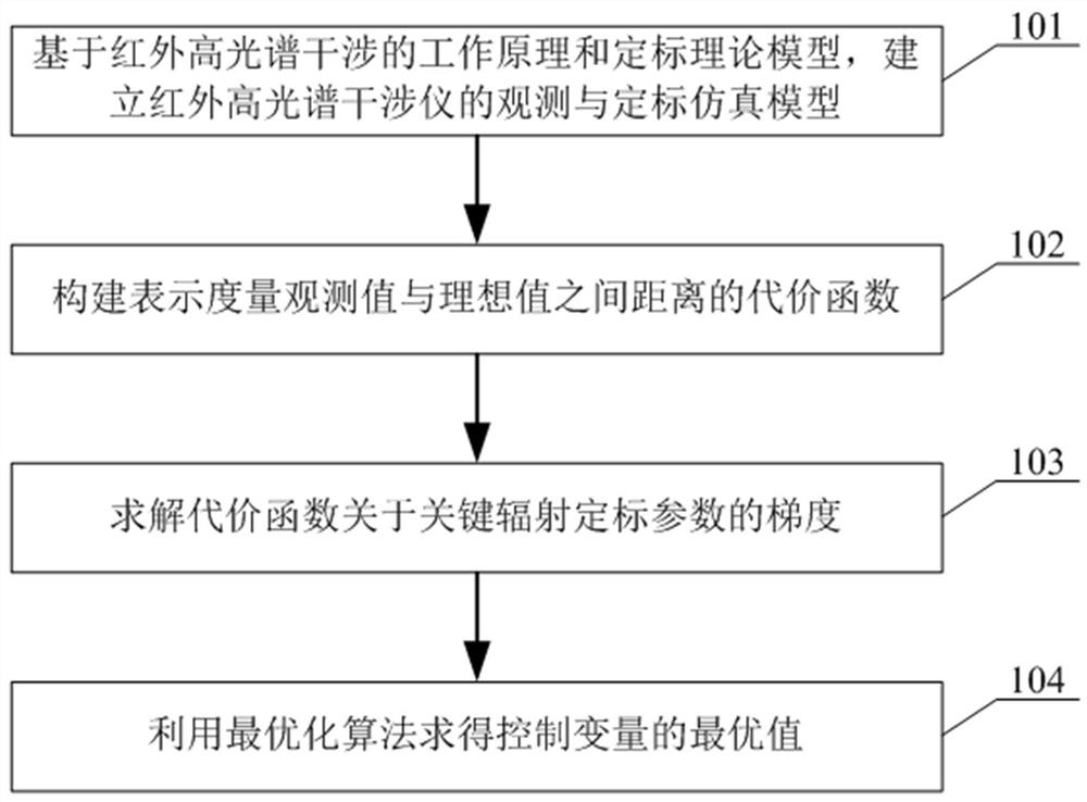
[0047] figure 1 For the on-orbit optimization method flow chart of the key calibration parameters of the infrared hyperspectral interferometer according to the present invention, the following will refer to figure 1 , the on-orbit optimization method for the key calibration parameters of the infrared hyperspectral interferometer of the present invention is described in detail.

[0048] First, in step 101, according to the instrument parameters and calibration parameters, the observation and calibration simulation model of the infrared hyperspectral interferometer is established.

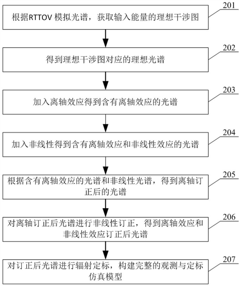
[0049] In the embodiment of the present invention, based on the working principle and calibration theoretical model of infrared hyperspectral interferometry, the observation and calibration simulation model of infrared hyperspectral interferometer is established. The main instrument effects considered are off-axis effects and nonlinear effects. Off-axis effects cause the spectrum to shift toward lo...

Embodiment 2

[0089] Embodiments of the present invention also provide an electronic device, Figure 5 It is a schematic diagram of the electronic equipment structure according to the present invention, such as Figure 5 As shown, the electronic device 50 of the present invention includes a processor 501 and a memory 502, wherein,

[0090] The memory 502 stores a computer program, and when the computer program is read and executed by the processor 501, it executes the steps in the embodiment of the above-mentioned on-orbit optimization method for key calibration parameters of the infrared hyperspectral interferometer.

Embodiment 3

[0092] Embodiments of the present invention also provide a computer-readable storage medium in which a computer program is stored, wherein the computer program is configured to perform the above-mentioned key calibration parameters of the infrared hyperspectral interferometer during operation. The steps in the embodiment of the orbit optimization method.

[0093] In this embodiment, the above-mentioned computer-readable storage medium may include but not limited to: U disk, read-only memory (Read-Only Memory, ROM for short), random access memory (Random Access Memory, RAM for short), mobile Various media that can store computer programs, such as hard disks, magnetic disks, or optical disks.


PUM


Abstract

The invention discloses an on-orbit optimization method for key calibration parameters of an infrared hyperspectral interferometer, and the method comprises the following steps: building an observation and calibration simulation model of the infrared hyperspectral interferometer according to instrument parameters and calibration parameters; constructing a cost function representing the distance between the measurement observation value and the ideal value; solving the gradient of the cost function about the key radiometric calibration parameter; and solving the optimal value of the control variable by using an optimization algorithm. According to the on-orbit optimization method for the key calibration parameters of the infrared hyperspectral interferometer, the optimal solution of the calibration parameters is searched through observation data and reference data after instrument calibration by using a change assimilation method, the idea is clear, the method is simple and feasible, and the on-orbit calibration precision is improved.

Description

technical field [0001] The invention relates to the technical field of infrared interferometers, in particular to an on-orbit optimization method for key calibration parameters of an infrared hyperspectral interferometer. Background technique [0002] Under the condition of existing instrument performance, the optimization of instrument calibration process is very important to improve its data accuracy. In the ground vacuum test, some parameters are generally measured by means of measurement, but it is difficult and expensive, and whether the ground measurement parameters can be used after the satellite is in orbit needs to be re-evaluated. Consider one parameter variation at a time during ground measurement, and fix other parameters, and the measurement result can be considered as a special solution. The actual situation is that after the satellite is in orbit, most of the instrument parameters change and cannot be measured, and need to be estimated by the parameters of th...

Claims


Application Information

Patent Timeline
IPC IPC(8): G01B9/02
CPCG01B9/02074
Inventor 陆其峰倪卓娅徐一树吴春强王富
Owner NAT SATELLITE METEOROLOGICAL CENT
Why Eureka
Try Eureka