Device and method for measuring dryness of gas-liquid two-phase fluid

A measurement device, gas-liquid technology, applied in liquid/fluid solid measurement, measurement device, measurement capacity, etc., can solve the problems of bubble size phase transition and phase balance effects, easy phase transition, and difficulty in micro bubbles, etc. Fast, responsive, and low-cost effects

Pending Publication Date: 2021-11-19
BEIJING INST OF SPACECRAFT SYST ENG
View PDF3 Cites 2 Cited by
  • Summary
  • Abstract
  • Description
  • Claims
  • Application Information

AI Technical Summary

Problems solved by technology

The disadvantage of this invention is that it only uses the tiny bubbles naturally formed in the phase separation process of the two-phase flow as tracer particles to complete the measurement, and lacks a means that can effectively control and adjust the size and quantity of the bubbles, especially For the gas-liquid two-phase flow formed by a single-component fluid, the gas phase and the liquid phase are in a saturated state, and the two phases are prone to phase transitions. The size of the bubble has a great influence on the phase transition and phase balance. The smaller the radius, the bubble more likely to condense and disappear into the liquid phase
Therefore, the tiny bubbles formed by gas-liquid mixing are difficult to survive in the saturated liquid phase, and cannot form reliable tracer bubbles in the liquid film, which affects normal measurement

Method used


Image

  • Device and method for measuring dryness of gas-liquid two-phase fluid
  • Device and method for measuring dryness of gas-liquid two-phase fluid
  • Device and method for measuring dryness of gas-liquid two-phase fluid

Examples


Embodiment 1

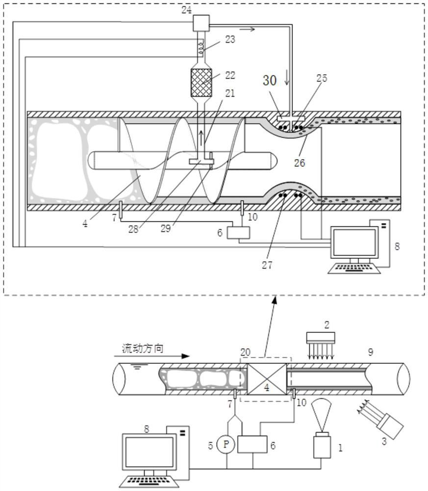
[0055] This embodiment provides a gas-liquid two-phase fluid dryness measurement device, see the attached figure 1 , including: cyclone 4, measuring tube 9, tracer bubble unit 20, image acquisition unit, pressure transmitter 5, differential pressure transmitter 6, industrial computer 8 and light source;

[0056] The outlet end of the measuring tube 9 is provided with a throat diameter section with a smaller inner diameter, and this throat diameter section is used as an accelerating nozzle 26;

[0057] The cyclone 4 is installed inside the inlet end of the measuring tube 9, that is, at the upstream end of the accelerating nozzle 26 of the measuring tube 9, and is used to make the gas-liquid two-phase fluid flow in a spiral rotation and generate a gap between the gas-liquid two-phase fluid. The separation force, so that the liquid phase moves to the tube wall of the measuring tube 9 under the action of centrifugal force, while the gas phase gathers in the central area of ​​the t...

Embodiment 2

[0071] A method for measuring the dryness of a gas-liquid two-phase fluid based on the above measuring device, the specific steps are as follows:

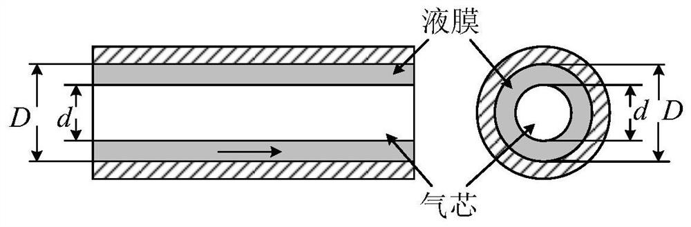
[0072] In the first step, the gas-liquid two-phase fluid in the swirling state enters the measuring tube 9, and the fixed cyclone 4 in the measuring tube 9 converts the gas-liquid two-phase fluid in the swirling state into two beams in the measuring tube 9. The single-phase fluid flowing in parallel in the tube 9, that is, the liquid phase flows against the inner wall of the measuring tube 9 to form a liquid film, and the gas phase flows in the center of the measuring tube 9 to form a gas core;

[0073] In the second step, tracer bubbles are planted in the liquid film at the accelerating nozzle 26 of the measuring tube 9, specifically as follows: open the gas mass flow controller 24 in the tracer bubble unit 20, and open the gas mass flow controller 24 in the central axis 28 of the cyclone 4. A small amount of gas enters the air-in...


PUM


Abstract

The invention discloses a device and a method for measuring dryness of gas-liquid two-phase fluid. The device comprises a cyclone, a measuring tube, a tracing bubble unit, an image acquisition unit, a differential pressure transmitter and an industrial personal computer, wherein the cyclone is mounted in the measuring tube and used for enabling the gas-liquid two-phase fluid to generate separating force between gas and liquid, the liquid phase flows along the inner wall of the measuring tube to form a liquid film, and the gas phase flows in the center of the measuring tube to form a gas core; the tracing bubble unit is used for planting a plurality of tracing bubbles into the liquid film; the differential pressure transmitter is used for measuring the pressure difference between the two ends of the cyclone; the image acquisition unit is used for acquiring images of a liquid film and a gas core in the measuring tube and an image of a motion trail of tracing bubbles, and the industrial personal computer is used for analyzing the images to obtain the flow velocity and the flow area of the liquid film and the flow of the liquid film, calculating the gas phase flow according to the flow of the liquid film and a pressure difference value, and finally determining a dryness value. The measurement process has the characteristics of visualization and good real-time performance.

Description

technical field [0001] The invention belongs to the technical field of thermal control, and in particular relates to a gas-liquid two-phase fluid dryness measurement device and method. Background technique [0002] In 1965, Gordon Moore proposed the famous "Moore's Law", that is, the number of transistors that can be accommodated on an integrated circuit will double every 18 months. The subsequent rapid development of large-scale integrated circuits confirmed this law. With the continuous improvement of circuit integration, the cooling problem of electronic chips is becoming more and more prominent. Since entering the 21st century, the heat flux density of integrated circuit chips has risen to 100-1000W / cm2. The effective heat dissipation method of electronic chips has become one of the core issues restricting the large-scale use of high-power devices, and plays a key role in energy power, machinery manufacturing, material chemical industry, electrical telecommunications, ...

Claims


Application Information

Patent Timeline
Patent Type & Authority Applications(China)
IPC IPC(8): G01F1/708G01F1/36G01F15/12
CPCG01F1/7086G01F1/36G01F15/125
Inventor 于新刚王正义牛棚满王栋徐侃苗建印
Owner BEIJING INST OF SPACECRAFT SYST ENG
Why Eureka
Try Eureka