

Current detection circuit and device applied to load resistor
A technology of current detection circuit and load resistance, applied in the direction of measuring current/voltage, measuring device, measuring electrical variables, etc., can solve the problems of difficult precision system application, low control accuracy, etc., to increase low-frequency gain and increase output impedance , the effect of increasing stability
- Summary
- Abstract
- Description
- Claims
- Application Information
AI Technical Summary
Problems solved by technology
Method used
Image

Examples
Embodiment Construction
[0036] In order to enable those skilled in the art to better understand the solutions of the present invention, the technical solutions in the embodiments of the present invention will be clearly and completely described below in conjunction with the drawings in the embodiments of the present invention. Obviously, the described embodiments are only It is a part of embodiments of the present invention, but not all embodiments. Based on the embodiments of the present invention, all other embodiments obtained by persons of ordinary skill in the art without making creative efforts belong to the protection scope of the present invention.
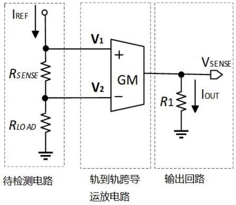
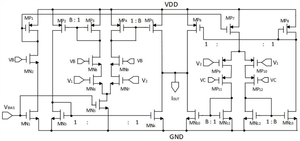
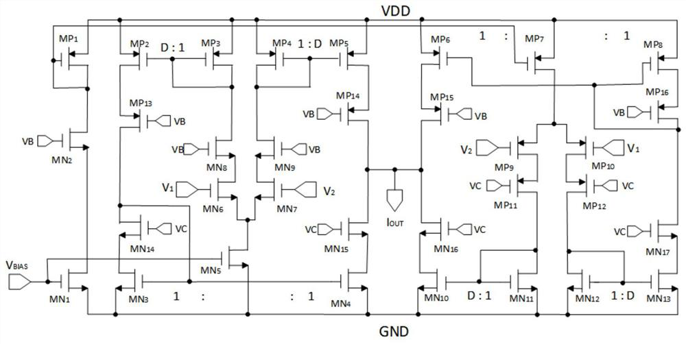
[0037] For ease of understanding, see figure 1 and figure 2 , the present invention provides an embodiment of a current detection circuit applied to a load resistance, including a rail-to-rail transconductance operational amplifier circuit GM and an output loop;
[0038] The input end of the rail-to-rail transconductance operational amplifier...
PUM
 Abstract
Description
Claims
Application Information