Wide-frequency-band vacuum microwave darkroom for near space high-speed target plasma environment ground simulation

A microwave anechoic chamber and plasma technology, applied in the direction of electromagnetic field characteristics, can solve problems such as failure to achieve, and achieve the effect of low outgassing rate and wide absorption frequency

Active Publication Date: 2021-11-19
HARBIN INST OF TECH
View PDF11 Cites 4 Cited by
  • Summary
  • Abstract
  • Description
  • Claims
  • Application Information

AI Technical Summary

Problems solved by technology

[0002] Since the aircraft will have different flight altitudes and flight speeds during real flight, the geometric shape of the surface plasmon sheath is also different, which requires that the electromagnetic wave band covered by the research needs to have an extremely wide wave band, usually in the MHz- However, the current publicly reported electromagnetic experiment system for ground simulation in the near space environment usually studies electromagnetic bands ranging from 1 to tens

Method used


Image

  • Wide-frequency-band vacuum microwave darkroom for near space high-speed target plasma environment ground simulation
  • Wide-frequency-band vacuum microwave darkroom for near space high-speed target plasma environment ground simulation
  • Wide-frequency-band vacuum microwave darkroom for near space high-speed target plasma environment ground simulation

Examples


Embodiment Construction

[0035] It should be noted that, in the case of no conflict, the embodiments of the present invention and the features in the embodiments can be combined with each other.

[0036] The present invention will be described in detail below with reference to the accompanying drawings and examples.

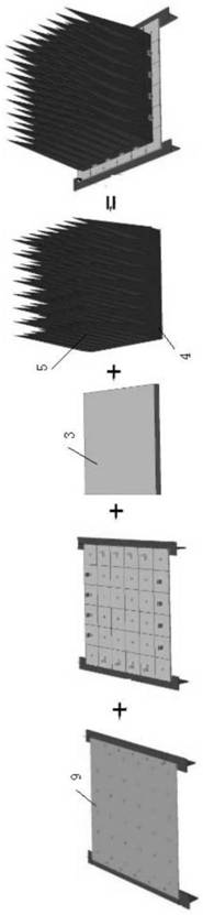
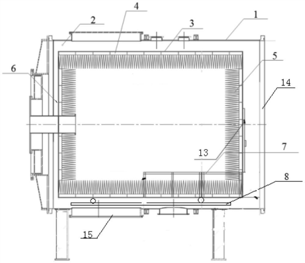
[0037] Such as Figure 1-Figure 8 As shown, a wide-band vacuum microwave anechoic chamber for ground simulation of a high-speed target plasma environment in adjacent space, including a vacuum tank 1, a microwave anechoic chamber framework 2, a support mechanism and a composite electromagnetic wave absorber;

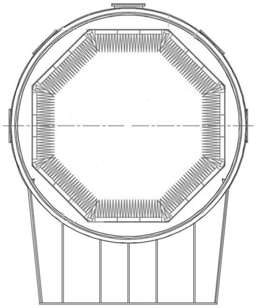
[0038] The microwave anechoic chamber skeleton 2 is arranged in the vacuum tank body 1, and is supported by a support mechanism in the vacuum tank body 1. The vacuum tank body 1 is a cylindrical structure, and one end of the vacuum tank body 1 is provided with There is a vacuum head flange 14;

[0039] The framework 2 of the microwave anechoic chamber includes three connecting sec...


PUM

PropertyMeasurementUnit
Lengthaaaaaaaaaa
Outer diameteraaaaaaaaaa
The inside diameter ofaaaaaaaaaa

Abstract

The invention provides a wide-frequency-band vacuum microwave darkroom for near space high-speed target plasma environment ground simulation, which comprises a vacuum tank body, a microwave anechoic chamber framework, a support mechanism and a composite electromagnetic wave absorber, the microwave anechoic chamber framework is arranged in the vacuum tank body, and one end of the vacuum tank body is provided with a vacuum end socket flange; the anechoic chamber framework comprises a plurality of connecting sections which are connected in sequence, and the connecting sections are connected to form a cylinder structure; a multistage nested flange is arranged at one end of the anechoic chamber framework, a wave-absorbing shielding door is arranged at the other end of the anechoic chamber framework, a plurality of composite electromagnetic wave absorbers are installed to completely cover the inner wall of the anechoic chamber framework, and each composite electromagnetic wave absorber is formed by compounding a ferrite tile, a matching layer and a pyramid wave-absorbing material through impedance matching. The ferrite tile, the matching layer and the pyramid wave-absorbing material are sequentially arranged from bottom to top. The wide-frequency-band vacuum microwave anechoic chamber can be provided and can be used for near space high-speed target surface plasma environment and electromagnetic communication research.

Description

technical field [0001] The invention belongs to the technical field of electromagnetic measurement, in particular to a wide-band vacuum microwave anechoic chamber used for ground simulation of high-speed target plasma environment in adjacent space. Background technique [0002] Since the aircraft will have different flight altitudes and flight speeds during real flight, the geometric shape of the surface plasmon sheath is also different, which requires that the electromagnetic wave band covered by the research needs to have an extremely wide wave band, usually in the MHz- However, the current publicly reported electromagnetic experiment system for ground simulation in the near space environment generally studies electromagnetic bands ranging from 1 to tens of GHz, and signals under low frequency conditions (such as MHz) are usually not considered. That is to say, there is no vacuum microwave anechoic chamber that can achieve an extremely wide band, so it is necessary to desi...

Claims


Application Information

Patent Timeline
IPC IPC(8): G01R29/08
Inventor 聂秋月张仲麟林澍张晓宁鄂鹏王晓钢李立毅
Owner HARBIN INST OF TECH
Why Eureka
Try Eureka