
Foam microstructure modeling method based on foaming process

A technology of foaming process and mesostructure, applied in 3D modeling, image data processing, special data processing applications, etc., can solve the problems of difficult microstructure of foam, low porosity, high cost, etc., and achieve easy shape Simple regulation and modeling methods and wide application range

Pending Publication Date: 2021-11-19
BEIHANG UNIV
View PDF0 Cites 0 Cited by
  • Summary
  • Abstract
  • Description
  • Claims
  • Application Information

AI Technical Summary

Problems solved by technology

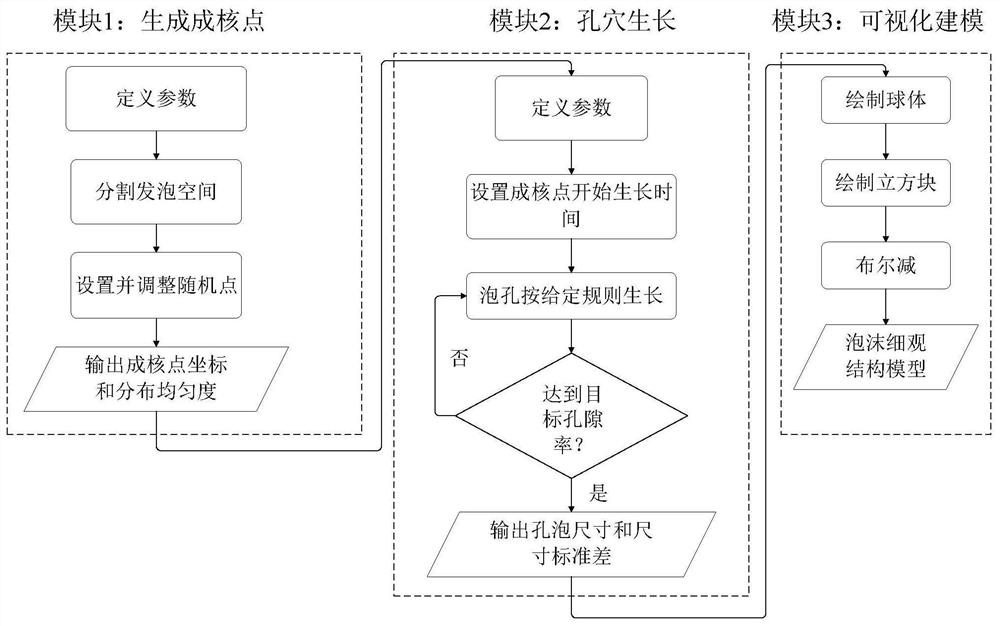
[0003] At present, there are mainly three ways to establish the microstructure of the foam: (1) the mesostructure unit cell established by the geometric method, which cannot reflect the complexity and randomness of the foam microstructure, so it is difficult to accurately simulate the foam microstructure Various performance
(2) The mesoscopic structure of the foam was established using the Voronoi stochastic model. This model treats the pore-strut and the pore wall as polygons and polyhedrons, respectively. This method is difficult to guarantee the gradual characteristics of the ligament and the real cross-sectional shape, and it is also difficult to characterize both. Foam with open and closed cells
(3) Slicing along the cross-section of carbon foam based on automatic continuous slicing technology, and taking pictures to record the cross-section information, and then synthesizing the three-dimensional structure. This method can obtain the precise microstructure of the foam, but it is expensive, and only a small piece can be obtained each time. Small-volume mesostructure, and it is difficult to accurately reproduce the microstructure of foams with low porosity and small-sized pores

Method used


Image

  • Foam microstructure modeling method based on foaming process
  • Foam microstructure modeling method based on foaming process
  • Foam microstructure modeling method based on foaming process

Examples


Embodiment

[0063] The superiority of the foam three-dimensional microstructure model modeling method of the present invention is verified.

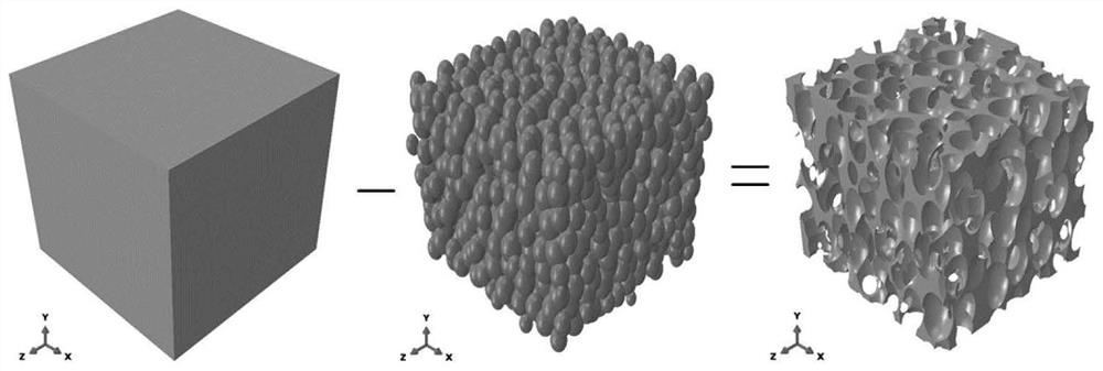
[0064] Consider the mesoscopic structural model of coal-based carbon foam with porosity equal to 0.8, ellipsoidal pores, and pore anisotropy rate equal to 1.83, and the size of the model is 2mm×2mm×2mm. figure 2 represents the porosity during cell growth The growth conditions of cells are equal to 0.01, 0.1, 0.4 and 0.8, respectively, where the ball represents the cell and the cube represents the foaming space. from porosity The distribution of nucleation points in the foaming space can be seen in the figure. image 3 Shown is the process of obtaining the foam mesostructure model by Boolean subtraction of the foaming region model and the cell model. First, all the cells are subjected to Boolean addition operation, and then the foaming region model is taken as the object, and the cell model after the Boolean addition is subtracted , to get the ...


PUM


Abstract

The invention provides a foam microstructure modeling method based on a foaming process. The foam microstructure modeling method comprises the following five steps including determining a foam foaming process, determining hole structure characteristics, generating nucleation points, growing and shaping holes, and visually modeling a hole structure. A foam microstructure model established through the method is highly similar to real foam and consistent in hole feature. The model established by the method can represent the randomness of a real foam hole structure, and the hole position distribution uniformity, the hole size uniformity, the hole number and the hole average size can be adjusted by adjusting parameters so as to obtain the model with very high similarity with the actual foam hole structure. The foam microstructure modeling method based on the foaming process is suitable for most open-cell and closed-cell foam materials, and the established microstructure model can accurately simulate the heat, electricity, sound, force and other properties of the foam materials.

Description

technical field [0001] The present invention relates to a modeling method for the mesostructure of foam materials, more specifically relates to a method based on the foaming process, which is more in line with the real pore structure, and is suitable for modeling the mesostructure of various natural and artificial foam materials The method belongs to the research field of porous materials. Background technique [0002] The apparent properties of porous materials depend directly on the shape and structure of pores, which is of great significance to the optimization of foam preparation process and foam material selection. Therefore, it is necessary to establish a microstructure model of the foam, and then study the properties of the foam material such as force, heat, sound, and electricity. [0003] At present, there are mainly three ways to establish the microstructure of the foam: (1) the mesostructure unit cell established by the geometric method, which cannot reflect the ...

Claims


Application Information

Patent Timeline
IPC IPC(8): G06F30/20G06T17/00
CPCG06F30/20G06T17/00
Inventor 程小全李小琪
Owner BEIHANG UNIV
Learn More