
Small-divergence-angle MicroLED device and MicroLED array

A small divergence, device technology, applied in instruments, identification devices, etc., can solve problems such as ratio drop, high black field brightness, pixel crosstalk, etc.

Pending Publication Date: 2021-11-19
廊坊广通电子设备有限公司
View PDF6 Cites 0 Cited by
  • Summary
  • Abstract
  • Description
  • Claims
  • Application Information

AI Technical Summary

Problems solved by technology

Light beyond the divergence angle will become stray light, resulting in decreased contrast, high black field brightness, pixel crosstalk, etc.

Method used


Image

  • Small-divergence-angle MicroLED device and MicroLED array
  • Small-divergence-angle MicroLED device and MicroLED array
  • Small-divergence-angle MicroLED device and MicroLED array

Examples


Embodiment 1

[0033] Example 1: Micro LED device with small divergence angle and its array for ultraviolet digital exposure

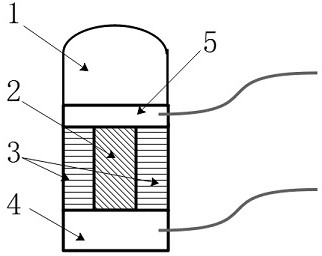
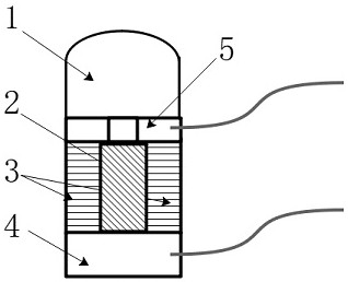
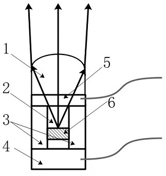
[0034] Figure 3 is a schematic diagram of the optical path and structure of the Micro LED device with a small divergence angle using a transmissive cathode electrode according to the present invention: please refer to Figure 3, the Micro LED device with a small divergence angle provided in Example 1 includes a micro-optical system 1, Micro LED particles 2. Isolation structure 3, pixel electrode 4, cathode electrode 5, electroluminescent quantum well structure 6, wherein the pixel electrode 4 is located at the bottom, MicroLED particles 2 and isolation structure 3 are placed above the pixel electrode 4, and the cathode electrode 5 is placed Above the Micro LED particle 2 and the isolation structure 3 , the micro-optical system 1 is placed above the cathode electrode 5 , and the electroluminescent quantum well structure 6 is a part of the Micro LED particle 2 and can em...


PUM

PropertyMeasurementUnit
Luminous wavelengthaaaaaaaaaa
Resistivityaaaaaaaaaa

Abstract

The invention provides a small-divergence-angle Micro LED device and a Micro LED array. The small-divergence-angle Micro LED device comprises a micro-optical system, Micro LED particles, an isolation structure, a pixel electrode and a cathode electrode. Due to LED light emitting principle factors, the light emitting divergence angle of the Micro LED device is too large, and light emitted by the Micro LED device and an array of the Micro LED device needs to have a small divergence angle due to the limitation of the numerical aperture of a projection lens in the industrial exposure field and the image projection field. The isolation structure and the micro-optical system are integrated on the Micro LED device to further converge the divergence angle, so that the Micro LED device can be applied to the industrial exposure field and the image projection field. By means of the high integration level and the controllable light field divergence angle, the Micro LED is finally pushed to the large-scale application stage of the industrial exposure field and the image projection field.

Description

technical field [0001] The invention relates to a Micro LED device with a small divergence angle and a Micro LED array. Background technique [0002] Micro LED technology generally refers to the technology in which tiny LED particles are powered and switched on and off through controllable electrodes. At present, the size of Micro LEDs ranges from microns to hundreds of microns. Generally, relatively large LED particles are called Mini LEDs, but the distinction between Mini LEDs and Micro LEDs is relatively vague. The Micro LED described in this patent contains micro LED particles with a diameter less than or equal to 500 microns. In the definition of some researchers, Mini LED also includes micro LED particles below 500 microns. Within the overlapping interval defined by both Micro LED and Mini LED, the Micro LED referred to in this article can also be named by the name of Mini LED. That is, it can also be understood that the Micro LED described in this article can be e...

Claims


Application Information

Patent Timeline
IPC IPC(8): G09F9/33
CPCG09F9/33
Inventor 孙雷张婧姣
Owner 廊坊广通电子设备有限公司
Learn More