Scanning electron microscope

An electron microscope and electron beam technology, applied in the microscope field, can solve the problems of low collection efficiency, space occupation, small space angle, etc., and achieve high reception efficiency

Pending Publication Date: 2021-11-19
FOCUS E BEAM TECH BEIJING CO LTD
View PDF0 Cites 1 Cited by
  • Summary
  • Abstract
  • Description
  • Claims
  • Application Information

AI Technical Summary

Problems solved by technology

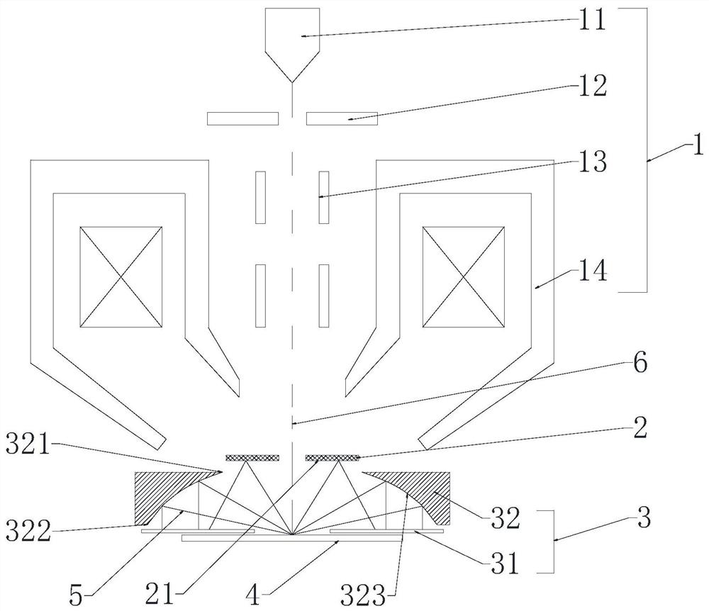
At present, cathodoluminescence detection is realized by a side-type cathodoluminescence detector, but the space angle received by the cathodoluminescence detector is small, and the collection efficiency is low
In addition, the side-type cathodoluminescence detector occupies space and blocks the paths of reflected electrons such as secondary electrons and backscattered electrons, so that scanning electron microscopes cannot detect cathodoluminescence and reflected electrons at the same time.

Method used


Image

  • Scanning electron microscope
  • Scanning electron microscope
  • Scanning electron microscope

Examples


Embodiment Construction

[0040] In order to make the purpose, technical solutions and advantages of the embodiments of the present invention more clear, the technical solutions in the embodiments will be clearly and completely described below in conjunction with the drawings in the embodiments of the present invention. The following embodiments are used to illustrate the present invention , but not to limit the scope of the present invention.

[0041] In the description of the present invention, it should be noted that the terms "upper", "lower", "front", "rear", "left", "right", "vertical", "inner", "outer" etc. The indicated orientation or positional relationship is based on the orientation or positional relationship shown in the drawings, and is only for the convenience of describing the present invention and simplifying the description, rather than indicating or implying that the referred device or element must have a specific orientation, or in a specific orientation. construction and operation, ...


PUM


Abstract

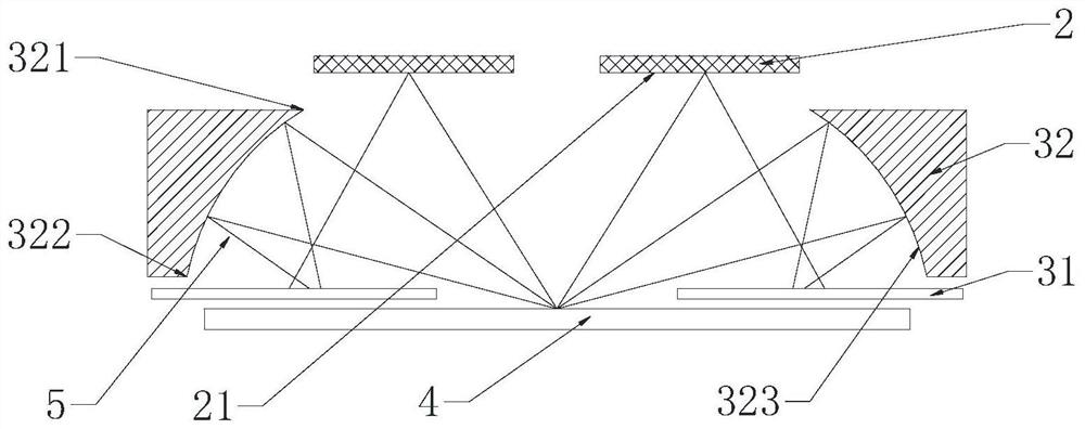
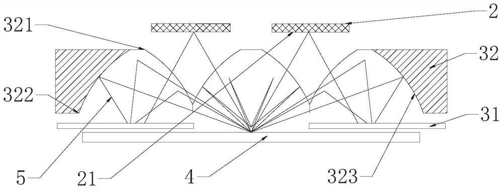
The invention discloses a scanning electron microscope, comprising: an electron optical lens barrel for generating an electron beam and focusing the electron beam on a sample; a first detector used for receiving electrons generated when the electron beam acts on the sample; and a second detector used for receiving photons generated when the electron beam acts on the sample. The second detector comprises a reflector and a photon detector, the reflector is annular and covers the periphery of the sample, and the reflector reflects photons generated on the sample to the photon detector. According to the scanning electron microscope provided by the invention, photons can be collected in a large range, and the receiving efficiency of the photon detector is high.

Description

technical field [0001] The invention belongs to the technical field of microscopes, in particular to a scanning electron microscope. Background technique [0002] In the prior art, the cathode fluorescence signal generated by the electron beam acting on the sample means that when the electron beam bombards the surface of the sample, in addition to secondary electrons, backscattered electrons, Auger electrons and X-rays, the emitted frequency is at Electromagnetic waves in the ultraviolet, infrared or visible light bands. The basic principle is that the electrons inside the sample are excited by the incident electrons to a high-energy state, and after a certain relaxation time, they transition back to a low-energy state and release energy, and part of the energy is emitted in the form of electromagnetic radiation. The physical process of cathodoluminescence of a sample under electron beam excitation is determined by its electronic structure, and the electronic structure is r...

Claims


Application Information

Patent Timeline
IPC IPC(8): H01J37/28H01J37/244
CPCH01J37/28H01J37/244H01J2237/2445H01J2237/2808H01J37/22H01J2237/2448
Inventor 刘莎何伟
Owner FOCUS E BEAM TECH BEIJING CO LTD
Why Eureka
Try Eureka