
Electromagnetic friction counteracting transmission auxiliary device

An auxiliary device and electromagnetic technology, applied in the field of machinery, can solve the problems of insufficient transmission efficiency of small-power motors, shortening the service life of the motor, and limited load capacity of the motor, so as to improve the service life and transmission efficiency, enhance the moving speed, and reduce the motor load Effect

Active Publication Date: 2021-11-19
苏州维斯勒姆智能科技有限公司
View PDF6 Cites 0 Cited by
  • Summary
  • Abstract
  • Description
  • Claims
  • Application Information

AI Technical Summary

Problems solved by technology

[0002] The transmission device is the source of power to drive the automatic operation of the mechanical device. The motor can drive the mechanical equipment to operate through the transmission shaft, and the gear and pulley are set on the transmission shaft to transmit power to the external mechanical equipment. However, the load capacity of the motor with different power is limited. Long-term high-load operation will cause a large loss to the motor and shorten the service life of the motor. In addition, in a special mechanical environment, when a high-power motor cannot be used, the transmission efficiency of a small-power motor is insufficient, which has a great impact on production. Large impact, the existing technology can not in the case of extremely low consumption, the auxiliary transmission of the motor to increase the load of the motor, improve the efficiency of the motor transmission, so people need a magnetic levitation enhanced power device and a transmission device to solve the above problems

Method used


Image

  • Electromagnetic friction counteracting transmission auxiliary device
  • Electromagnetic friction counteracting transmission auxiliary device
  • Electromagnetic friction counteracting transmission auxiliary device

Examples


Embodiment

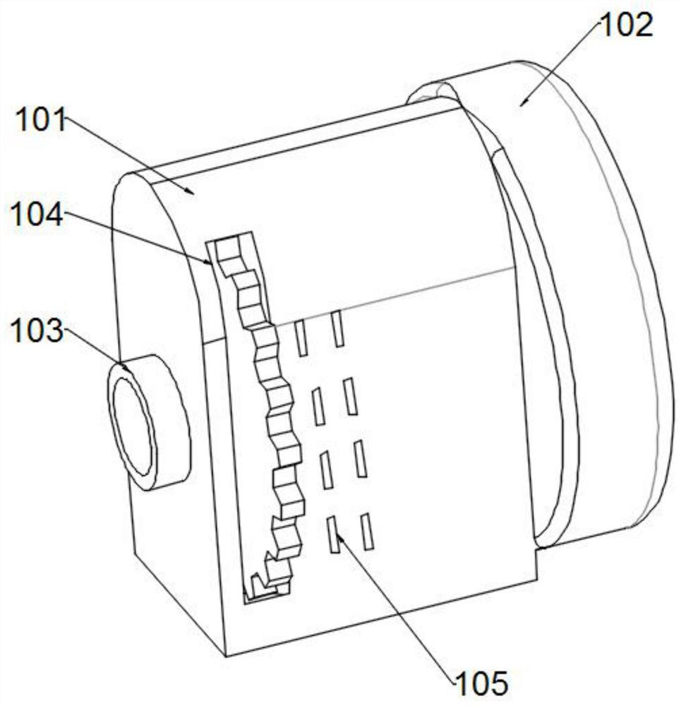
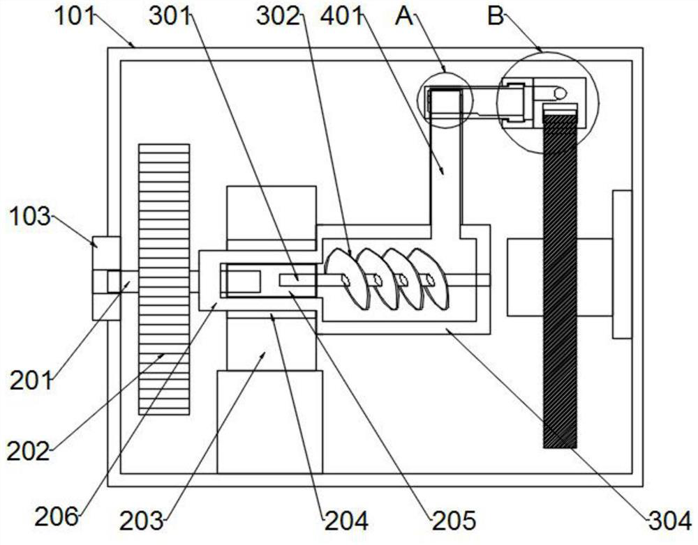
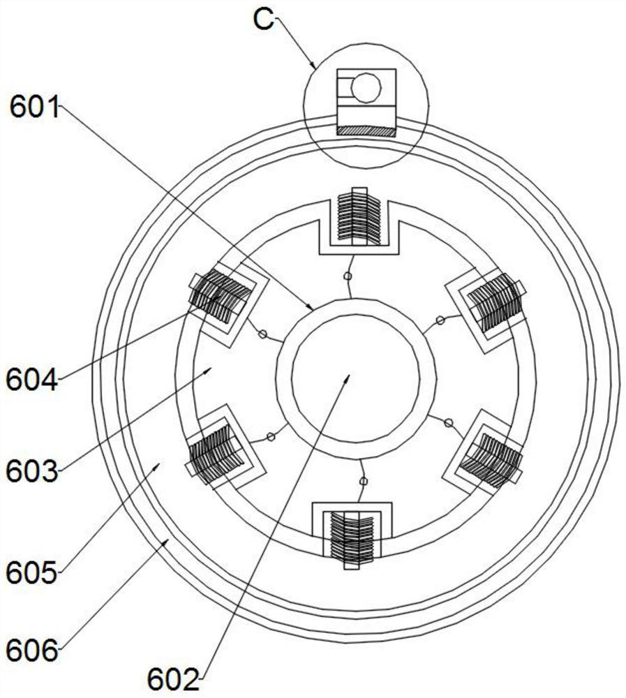
[0029] Example: such as Figure 1-7 As shown, an electromagnetic friction offset transmission auxiliary device includes a support assembly, a transmission assembly, a pneumatic assembly, an air flow assembly, a drive auxiliary assembly, and an electromagnetic centrifugal offset assembly. The support assembly is located at the outermost side of the entire device to support and protect the interior of the device. The role of the parts, the transmission component is installed at one end of the support component, and the transmission component plays the role of providing power for the external machine. Components, the airflow component plays the role of transmitting air flow, the side of the airflow component away from the pneumatic component is provided with a driving auxiliary component, the driving auxiliary component plays an auxiliary role in strengthening the transmission effect of the device, and the end of the supporting component far away from the transmission component is...


PUM


Abstract

The invention discloses an electromagnetic friction counteracting transmission auxiliary device, and belongs to the technical field of machinery. The electromagnetic friction counteracting transmission auxiliary device comprises a supporting assembly, a transmission assembly and a pneumatic assembly, wherein the supporting assembly is located on the outermost side of the whole device, the transmission assembly is arranged at one end in the supporting assembly, and the pneumatic assembly is arranged on the side of the transmission assembly. According to the invention, the electromagnetic friction counteracting transmission auxiliary device is scientific and reasonable, can efficiently assist an external motor or other transmission devices, reduce the load of the motor, enable the motor to operate for a long time, prolong the service life of the motor, improve the transmission efficiency of the motor, effectively assist the motor to enhance the transmission strength, and enable a low-power motor to achieve the same effect in an environment where a high-power motor is difficult to install; and according to the device, centrifugal force generated by rotation of the driving block is counteracted through magnetic force, friction resistance of the sliding rail groove to the driving block is reduced to the minimum, the moving speed of the driving block is greatly increased, and then the power assisting effect of the device on the motor transmission shaft is effectively enhanced.

Description

technical field [0001] The invention relates to the technical field of machinery, in particular to an electromagnetic friction offset transmission auxiliary device. Background technique [0002] The transmission device is the source of power to drive the automatic operation of the mechanical device. The motor can drive the mechanical equipment to operate through the transmission shaft, and the gear and pulley are set on the transmission shaft to transmit power to the external mechanical equipment. However, the load capacity of the motor with different power is limited. Long-term high-load operation will cause a large loss to the motor and shorten the service life of the motor. In addition, in a special mechanical environment, when a high-power motor cannot be used, the transmission efficiency of a small-power motor is insufficient, which has a great impact on production. Large impact, the existing technology can not under the condition of extremely low consumption, assist th...

Claims


Application Information

Patent Timeline
Patent Type & Authority Applications(China)
IPC IPC(8): H02K7/10F16H33/02F16D41/063F16C41/00F16C32/04F04D19/00
CPCH02K7/10F16H33/02F16D41/063F16C32/0478F16C32/0451F16C32/0493F16C41/001F16C41/008F04D19/002F16C2233/00F16C2237/00
Inventor 不公告发明人
Owner 苏州维斯勒姆智能科技有限公司
Learn More