Automatic lathe for nicking tool accessory machining

A technology for automatic lathes and accessories, which is applied to the accessories of tool holders, metal processing equipment, manufacturing tools, etc. It can solve the problems of no locking cap, single processing, etc., and achieve the effect of reducing cost and simple processing logic

Active Publication Date: 2021-11-23
嘉兴力骏五金制品有限公司
View PDF6 Cites 2 Cited by
  • Summary
  • Abstract
  • Description
  • Claims
  • Application Information

AI Technical Summary

Problems solved by technology

[0002] Art carving knife is a common product in the market. There is a construction of art carving knife on the market, which includes a rod, a knife holder and a blade. The blade is installed on the knife holder and fixed by a locking cap. The knife holder and the rod are fixed. Cap production is a single process and there is no specific machine tool for the production of locking caps

Method used


Image

  • Automatic lathe for nicking tool accessory machining
  • Automatic lathe for nicking tool accessory machining
  • Automatic lathe for nicking tool accessory machining

Examples


Embodiment Construction

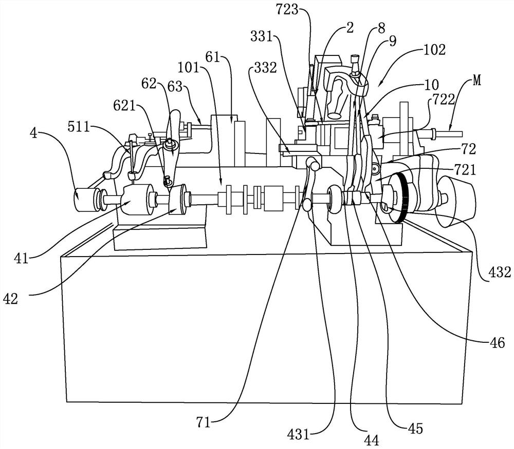
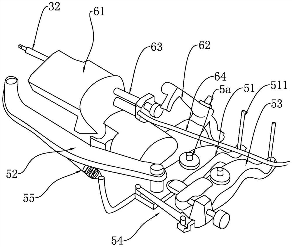
[0047] refer to Figure 1 to Figure 10 Embodiments of the present invention will be further described.

[0048] The invention is used for processing the cap with hollow structure. Its specific structure is:

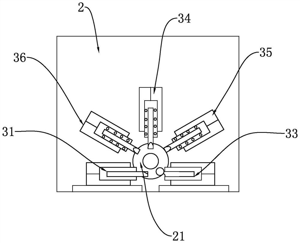
[0049] The lathe 1 has a workbench, a main machine 2 for providing power, and a forming device for processing caps.

[0050] The main machine 2 has a clamp 21 and a motor, the clamp 21 is rotatably connected to the main machine 2, and the clamp 21 is driven by the motor to control its rotation. The main machine 2 is connected front and back, and the clamp 21 is installed in front of the main machine 2. The hollow pipe W used for forming the cap can be inserted from the rear, and then clamped by the clamp 21. The main machine 2 also has a The cutter for cutting the section of the pipe W pulls the pipe W in front and ejects it when the pipe W behind is pushed forward.

[0051] The forming device is placed on the workbench, and it includes a first cutter 31 for turning t...


PUM


Abstract

The invention relates to the technical field of nicking tool production equipment, in particular to an automatic lathe for nicking tool accessory machining. The lathe is provided with a main machine providing power and a forming device, the main machine is provided with a clamp and a motor driving a main machine body to rotate, and the clamp is controlled by rotation of the main machine. The forming device comprises a first cutter for turning the outer wall of a cap, a second cutter for tapping the inner wall of the cap, a third cutter for pressing a spline on the outer wall of the cap, a fourth cutter for turning the cap to form a connecting part, a fifth cutter for chamfering the outer wall of the front end of the cap, and a sixth cutter for cutting the machined cap and enabling the cap to fall off from the clamp. A linkage structure drives the first cutter, the second cutter, the third cutter, the fourth cutter, the fifth cutter and the sixth cutter to synchronously machine the cap in sequence while being controlled by the motor to move, so that the cap form a finished product after falling off from the clamp. The lathe is simple in structure, reasonable, and high in production efficiency.

Description

technical field [0001] The invention relates to the technical field of carving knife production equipment, more specifically, it relates to an automatic lathe used for machining carving knife accessories. Background technique [0002] Art carving knife is a common product in the market. There is a construction of art carving knife on the market, which includes a rod, a knife holder and a blade. The blade is installed on the knife holder and fixed by a locking cap. The knife holder and the rod are fixed. Cap production is a single process with no specific machine tool for producing locking caps. Contents of the invention [0003] Aiming at the deficiencies in the prior art, the object of the present invention is to provide an automatic lathe for machining cutter accessories with simple structure, reasonable structure and high production efficiency. [0004] To achieve the above object, the present invention provides the following technical solutions: [0005] An automatic...

Claims


Application Information

Patent Timeline
Patent Type & Authority Applications(China)
IPC IPC(8): B23B5/00B23B25/00B23P23/02
CPCB23B5/00B23B25/00B23P23/02
Inventor 郑嘉玮
Owner 嘉兴力骏五金制品有限公司
Why Eureka
Try Eureka