An intelligent maintenance automatic lifting and shifting device

A technology of automatic lifting and shifting device, applied in the directions of brake parts, transportation and packaging, brake actuators, etc., can solve the problems of difficult to carry, intelligent detection of mechanical accuracy discount, etc., to achieve convenient assembly and maintenance, overall structure combination Simple, accurate detection effect

Active Publication Date: 2021-12-28
温州宇岚科技有限公司
View PDF11 Cites 0 Cited by
  • Summary
  • Abstract
  • Description
  • Claims
  • Application Information

AI Technical Summary

Problems solved by technology

[0003] Furthermore, in the process of intelligent maintenance, the displacement device for auxiliary maintenance equipment is indispensable. However, there are many high-precision displacement devices in the prior art, but the position displacement device is limited by the volume of the target device. The size can play its role, so that it is difficult for a general large intelligent detection machine to be equipped with a suitable displacement device, which greatly reduces the accuracy of the intelligent detection machine

Method used


Image

  • An intelligent maintenance automatic lifting and shifting device
  • An intelligent maintenance automatic lifting and shifting device
  • An intelligent maintenance automatic lifting and shifting device

Examples


Embodiment 1

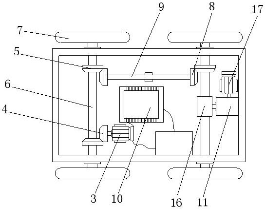
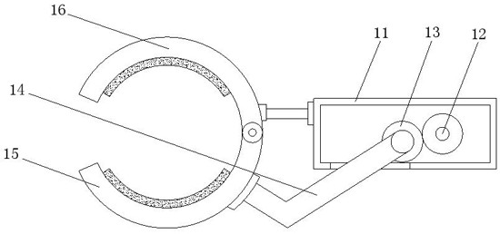
[0029] Embodiment 1, according to Figure 1-3 , Figure 5 , when using the moving function, the external control device sends a signal to the control assembly 10 installed inside the mobile device 2, and the control assembly 10 controls the rotation of the first motor 3 after receiving the signal, and the rotation of the output end of the first motor 3 drives the first cone The gear 4 rotates, through the engagement between the first bevel gear 4 and the second bevel gear 5, and then drives the first transmission rod 6 to rotate, the two first transmission rods 6 are connected by the second transmission rod 9, and the first transmission rod 6 is connected by the second transmission rod 9. A transmission rod 6 drives a total of four wheels 7 installed at both ends to move inside the track 1. When the mobile device 2 is about to move to a designated position, the second motor 17 is controlled by the control component 10 to operate, and the second motor 17 outputs The rotation o...

Embodiment 2

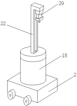
[0030] Embodiment 2, according to figure 1 , Figure 4 with Figure 6-7 , when using the rotation function, an external control device sends a signal to the controller 28, and the controller 28 controls the action of the third motor 24 after receiving the signal, and drives the turntable 25 to rotate through the rotation of the output end of the third motor 24, and then uses the sphere 23 The contacting turntable 25 drives the ball 23 to rotate to change the angle, and then drives the rotating rod 21 to rotate, and further drives the slide rail 22 to rotate. When the angle rotates to the desired angle, the controller 28 sends a signal to control the output of the first electric cylinder 26. end action, drive the brake plate 27 to contact with the sphere 23, realize the locking of the rotation angle, and when the rotation rod 21 rotates, the controller 28 can also act through the controlled second electric cylinder 29 and be installed on the connecting block 30 The advanced d...


PUM


Abstract

The invention discloses an intelligent maintenance automatic lifting and shifting device, which includes a track, a moving device is installed inside the track, a first motor is fixedly installed inside the moving device, and the output end of the first motor is fixed A first bevel gear is installed, the first bevel gear meshes with a second bevel gear, the center of the second bevel gear runs through a first transmission rod, and a wheel is fixedly installed on one end of the first transmission rod, so The second bevel gear meshes with a third bevel gear, the center of the third bevel gear runs through a second transmission rod, the inside of the moving device is fixedly installed with a control assembly, and the inside of the moving device is fixedly installed with a brake The first gear is installed inside the brake box. The present invention has a compact internal structure and a high degree of integration. At the same time, the overall structure is simple and convenient for assembly and maintenance, and it is effective for general large-scale machinery to achieve high-precision displacement. control.

Description

technical field [0001] The invention relates to the technical field of intelligent detection, in particular to an automatic lifting and shifting device for intelligent maintenance. Background technique [0002] In the field of maintenance, artificial intelligence is mainly used in fault diagnosis, maintenance training, maintenance management, maintenance evaluation, etc., in which maintenance management includes maintenance decision-making, maintenance planning, determination of preventive maintenance intervals, etc., directly using artificial intelligence in the maintenance process The fields of intelligence mainly include: a. Intelligent diagnosis, with the help of artificial intelligence methods, analyze and judge the faults of complex systems on the basis of monitoring, determine the location and cause of the fault, and give solutions; b. Robotics, The use of robot vision and pattern recognition itself requires artificial intelligence methods to solve, such as allowing r...

Claims


Application Information

Patent Timeline
Patent Type & Authority Patents(China)
IPC IPC(8): F16M11/04F16M11/08F16M11/18F16M11/28F16M11/42B65G35/00F16D65/06F16D65/14F16D121/24
CPCF16M11/04F16M11/08F16M11/18F16M11/28F16M11/42B65G35/00F16D65/06F16D65/14F16D2121/24
Inventor 平庆义郭连坤
Owner 温州宇岚科技有限公司
Why Eureka
Try Eureka