
Double-sided reciprocating film coating device

A coating device and double-sided technology, applied in the field of double-sided reciprocating coating devices, can solve the problems of low utilization rate of effective space, high cost, low efficiency, etc., and achieve the effects of improving effective space utilization, reducing energy consumption and reducing cost

Active Publication Date: 2021-11-23
SUZHOU TAONE SINCERE NANOMATERIAL TECH CO LTD +1
View PDF28 Cites 3 Cited by
  • Summary
  • Abstract
  • Description
  • Claims
  • Application Information

AI Technical Summary

Problems solved by technology

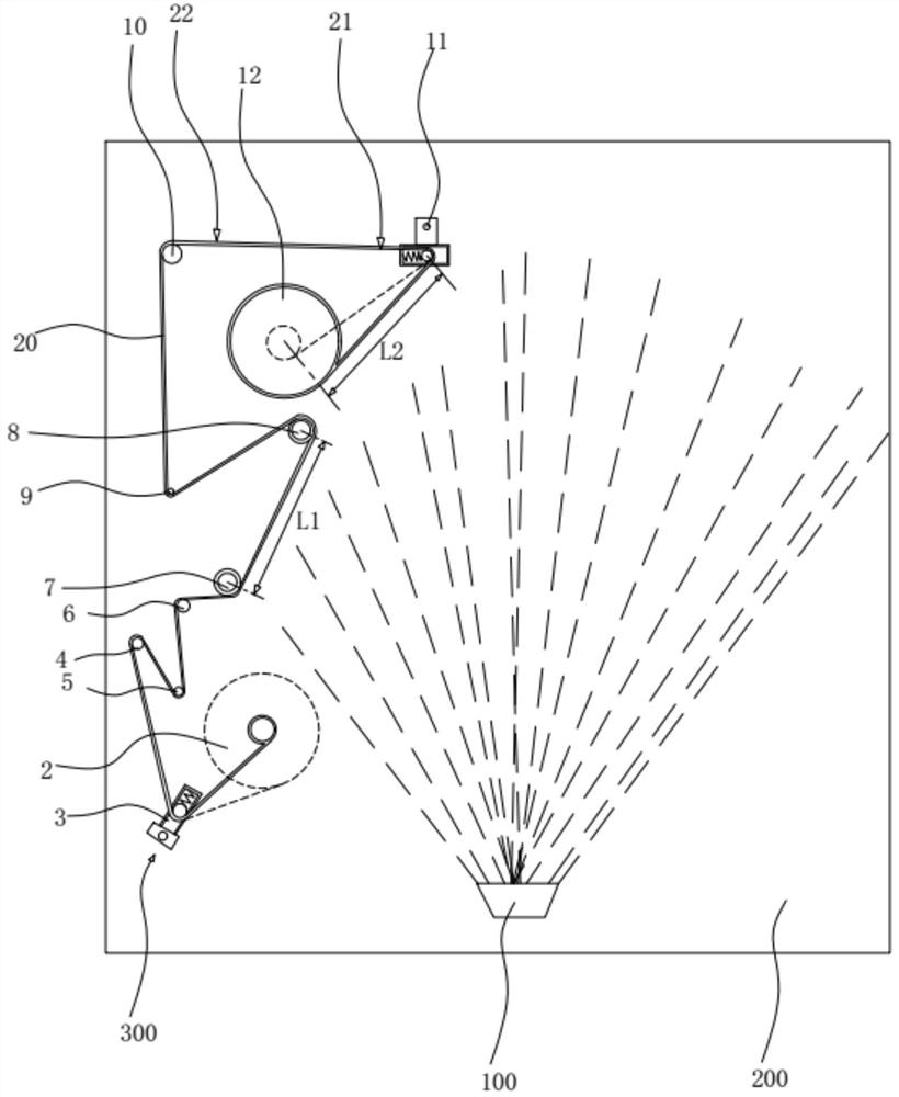
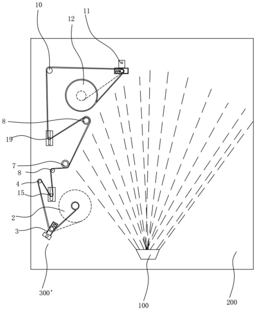
[0004] Therefore, one of the purposes of the present invention is to provide a double-sided reciprocating film coating device to solve the problem that the existing film coating device must have multiple evaporation sources or need to perform film inversion operations to achieve double-sided film coating. Low cost, high cost, low efficiency, small production capacity and other issues

Method used


Image

  • Double-sided reciprocating film coating device
  • Double-sided reciprocating film coating device
  • Double-sided reciprocating film coating device

Examples


Embodiment 1

[0088] Configure 2 sets of winding equipment of the present invention in the cylindrical vacuum chamber, and the winding width (transverse width) of the flexible strip is the same as that of the current single-sided winding equipment, so in a cylindrical vacuum chamber with the same size, The production efficiency of the winding equipment of this embodiment is 4 times of the present single-sided winding equipment production efficiency, and wherein, double-sided steaming (splashing) is 2 times, and 2 sets of winding equipments are 2 times again.

Embodiment 2

[0090] Configure 3 sets of winding equipment of the present invention in the cylindrical vacuum chamber, the winding width (transverse width) of the flexible strip is small with the current single-sided winding equipment (according to the vacuum chamber configuration of 1.6 meters in diameter, the width of the present embodiment Width size is the width of the single-sided winding equipment of 1.0 meters), so in a cylindrical vacuum chamber with the same size, the production efficiency of the winding equipment of this embodiment is the highest production efficiency of the current single-sided winding equipment. 5 times, of which, double-sided steaming (splashing) is 2 times, 3 sets of winding equipment is 3 times, the width is 1.0 meters, and the efficiency ratio=2*3*1.0 / 1.2=5.

Embodiment 3

[0092] Configure 4 sets of winding equipment of the present invention in the cylindrical vacuum chamber, and the winding width (transverse width) of the flexible strip is small with the current single-sided winding equipment (according to the vacuum chamber configuration of 1.6 meters in diameter, the width of the present embodiment Width size is 0.75 times the width of the single-sided winding equipment), so in a cylindrical vacuum chamber with the same size, the production efficiency of the winding equipment of this embodiment is the highest production efficiency of the current single-sided winding equipment. 6 times, of which, double-sided steaming (splashing) is 2 times, 4 sets of winding equipment is 4 times, the width is 0.83, and the efficiency ratio=2*4*0.83 / 1.2=5.53.

[0093] Table 1 The number of winding equipment configurations of the present invention and the productivity comparison table of single-sided winding equipment

[0094] Configuration sets Wid...


PUM


Abstract

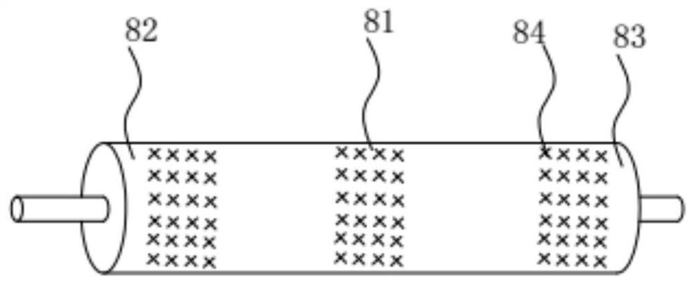
The invention discloses a double-sided reciprocating film coating device which comprises a vacuum chamber, an emission source system, at least one set of winding equipment and a driving mechanism. The winding equipment comprises a first winding roller, a first tension elastic roller, a first constant-speed transmission roller, a second constant-speed transmission roller, a second tension elastic roller and a second winding roller which are sequentially arranged on a conveying path of a flexible strip; the first winding roller and the second winding roller are winding (unwinding) rollers and are master (slave) power rollers of each other; the first constant-speed transmission roller and the second constant-speed transmission roller are master and slave constant-speed transmission rollers of each other; and a first surface, between the first constant-speed transmission roller and the second constant-speed transmission roller, of the flexible strip and a second surface, between the first winding roller and the first tension elastic roller, of the flexible strip both face the emission source system. The invention can solve the problems of low utilization rate of the effective space in a vacuum chamber, high cost, low efficiency, small productivity and the like caused by the fact that an existing film coating device needs to be provided with at least two evaporation sources (groups) to implement double-sided film coating.

Description

technical field [0001] The invention relates to the field of coating equipment, in particular to a double-sided reciprocating coating device. Background technique [0002] Vacuum coating technology is generally divided into two categories, namely physical vapor deposition (PVD) technology and chemical vapor deposition (CVD) technology. Whether it is PVD or CVD technology, the current single evaporation source (group) of the flexible winding system corresponds to a single surface Coating and winding systems are mature technologies and are widely used in the flexible substrate coating industry. However, when double-sided coating is necessary, only one side can be coated first, and then the machine is turned off to unload the film. After the entire roll of film that has been coated on one side is changed and poured on the film pouring machine, the material is reloaded for secondary coating. These structures are produced in this way, which is time-consuming, labor-intensive, an...

Claims


Application Information

Patent Timeline
Patent Type & Authority Applications(China)
IPC IPC(8): C23C14/56C23C14/30C23C14/28C23C14/35C23C14/26C23C14/32
CPCC23C14/562C23C14/30C23C14/28C23C14/35C23C14/26C23C14/325C23C14/0021Y02E60/10
Inventor 钱若棨钱敬吉
Owner SUZHOU TAONE SINCERE NANOMATERIAL TECH CO LTD
Learn More