Stop-free valve electric actuator replacing method, debugging assembly and electric actuator

A technology for electric actuators, replacement methods, applied in the direction of engine components, valve details, valve devices, etc., to achieve the effects of speeding up, portability, and simple structure

Pending Publication Date: 2021-11-23
XIAMEN HUAXIA INT POWER DEV +1
View PDF0 Cites 0 Cited by
  • Summary
  • Abstract
  • Description
  • Claims
  • Application Information

AI Technical Summary

Problems solved by technology

As for important valves, part or all of the production system can only be shut down, and the electric actuators should be replaced immediately. The indirect economic losses often reach hundreds of thousands of yuan or more.

Method used


Image

  • Stop-free valve electric actuator replacing method, debugging assembly and electric actuator
  • Stop-free valve electric actuator replacing method, debugging assembly and electric actuator
  • Stop-free valve electric actuator replacing method, debugging assembly and electric actuator

Examples


Embodiment 1

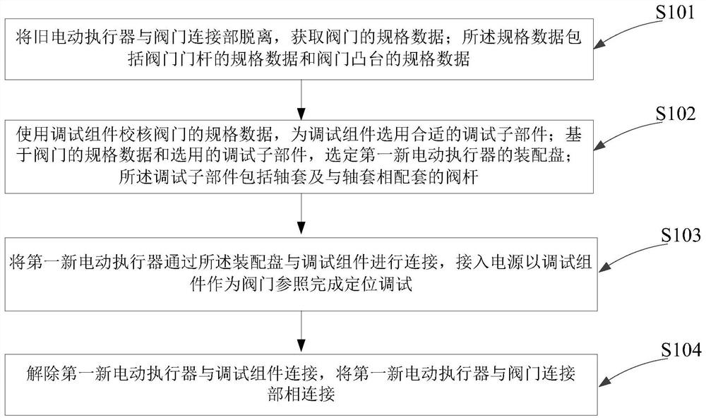
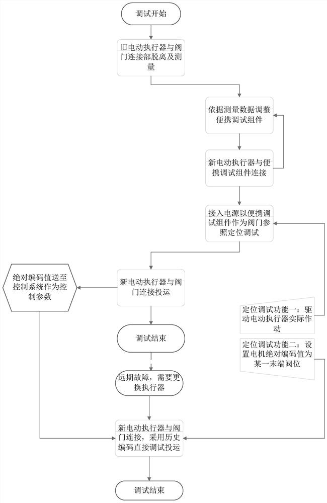
[0052] see figure 1 and figure 2 As shown, a replacement method of valve electric actuator without shutdown, including:

[0053] S101, disengage the old electric actuator from the valve connection part, and obtain the specification data of the valve; the specification data includes the specification data of the valve stem and the specification data of the valve boss;

[0054] S102, use the debugging component to check the specification data of the valve, and select a suitable debugging sub-component for the debugging component; based on the specification data of the valve and the selected debugging sub-component, select the assembly plate of the first new electric actuator; the debugging sub-component The components include the shaft sleeve and the valve stem matched with the shaft sleeve;

[0055] S103, connect the first new electric actuator with the debugging component through the assembly plate, connect the power supply and use the debugging component as a valve referen...

Embodiment 2

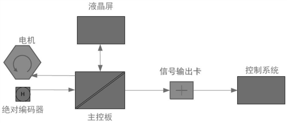
[0089] see image 3 As shown, an electric actuator includes a LCD screen, a main control board, a motor, an absolute encoder and a signal output card;

[0090] The liquid crystal screen is used to receive the input absolute code value corresponding to the valve positions at both ends of the valve, and send the absolute code value to the main control board;

[0091] The main control board is used to receive the absolute code value corresponding to the valve positions at both ends of the valve sent by the liquid crystal screen, and control the motor to rotate;

[0092] The absolute encoder is used to detect the amount of rotation of the motor, and output serial port signals or other electrical signals to the main control board;

[0093] The main control board is also used to send the serial port signal or other electrical signals to the signal output card;

[0094] The signal output card is used to receive the signal output by the main control board, and convert it into a 4-20...


PUM


Abstract

The invention discloses a stop-free valve electric actuator replacing method, a debugging assembly and an electric actuator. The method comprises the steps that an old electric actuator is separated from a valve connecting part, and specification data of a valve are obtained; the specification data comprise specification data of a valve rod and specification data of a valve boss; the specification data of the valve are checked through the debugging assembly, and a proper debugging sub-component is selected for the debugging assembly; an assembly disc of a first new electric actuator is selected on the basis of the specification data of the valve and the selected debugging sub-component; the debugging sub-component comprises a shaft sleeve and a valve rod matched with the shaft sleeve; the first new electric actuator is connected with the debugging assembly through the assembly disc, a power source is connected, and positioning debugging with the debugging assembly as a valve reference is completed; and the connection between the first new electric actuator and the debugging assembly is removed, and the first new electric actuator is connected with the valve connecting part. According to the stop-free valve electric actuator replacing method, replacement of the valve electric actuator can be achieved under the condition that a production system is not stopped.

Description

technical field [0001] The invention relates to the technical field of electric actuators for automation instruments, in particular to a method for replacing electric actuators for valves without shutdown, a debugging component and an electric actuator. Background technique [0002] In the industrial production process system, a large number of electric actuators are used as the operating actuators of pipeline valves to realize the opening and closing of various process media in the pipeline and the linear adjustment of the interval opening, thereby completing the automation process of the entire process system. The more common ones are boiler feed water valves in power plants, feed valves for reactors in chemical plants, etc. Under normal circumstances, the opening and closing time of the valve is very different. For example, the boiler feed water valve in a power plant needs to be kept fully open during normal operation of the generator set, and it is only urgently moved t...

Claims


Application Information

Patent Timeline
IPC IPC(8): F16K31/04F16K37/00
CPCF16K31/04F16K37/0091
Inventor 沈志刚王许许积庄
Owner XIAMEN HUAXIA INT POWER DEV
Why Eureka
Try Eureka