Wafer test board, wafer test system and wafer test method

A chip testing, chip technology, applied in the direction of semiconductor/solid-state device testing/measurement, single semiconductor device testing, electrical measurement, etc., can solve problems affecting signal integrity, capacitive and inductive interference, etc., to maintain integrity, The effect of simple and compact structure

Active Publication Date: 2021-11-23
APLUS SEMICON TECH CO LTD
View PDF7 Cites 0 Cited by
  • Summary
  • Abstract
  • Description
  • Claims
  • Application Information

AI Technical Summary

Problems solved by technology

[0004] For this reason, the present invention proposes a chip test board, which can solve the problem that the signal integrity of

Method used


Image

  • Wafer test board, wafer test system and wafer test method
  • Wafer test board, wafer test system and wafer test method
  • Wafer test board, wafer test system and wafer test method

Examples


Example Embodiment

[0030] Embodiments of the present invention will be described in detail below, and examples of the embodiments are illustrated in the drawings, in which the same or similar reference numerals represent the same or similar elements or elements having the same or similar functions. The following is exemplary, and is intended to be illustrative of the invention, not to be construed as limiting the invention.

[0031] In the description of the present invention, it is to be understood that the terms "center", "longitudinal", "horizontal", "length", "width", "thickness", "upper", "under", "front", " After "," left "," right "," vertical "," horizontal "," top "," bottom "," internal "," outside "," clockwise "," counterclock "," axial " , "Radial", "circumferential" or the like, is based on the orientation or positional relationship shown in the drawings, is merely described in order to facilitate the description of the present invention, rather than indicating or implying means of mea...


PUM


Abstract

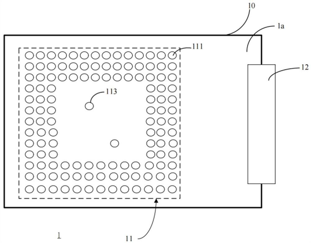
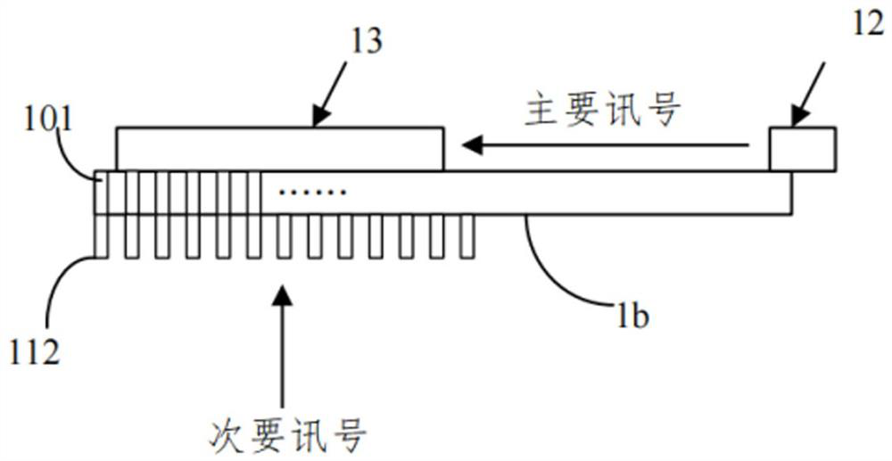
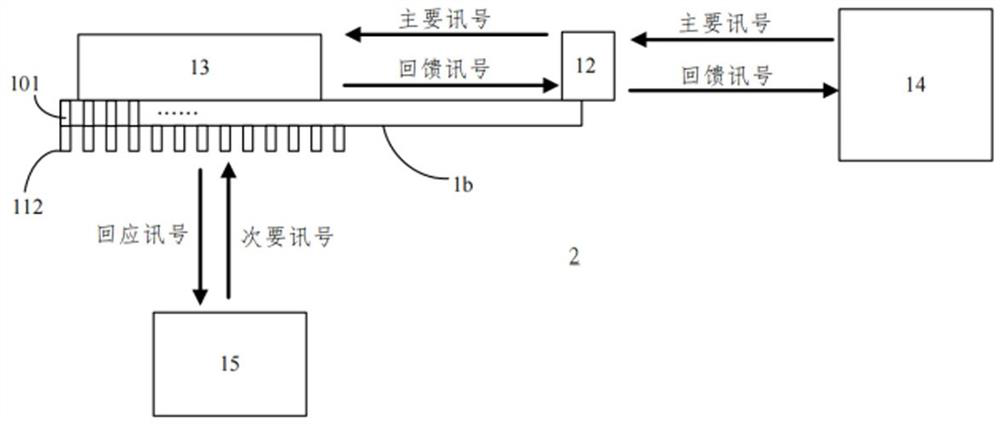
The invention discloses a wafer test board, which is used for testing a wafer according to a primary signal and a secondary signal, and comprises a body provided with a plurality of first through holes communicated with the two sides of the body; a wafer testing area which is arranged on one side of the body; and a main signal connector which is arranged on the same side of the body and is used for being connected with the wafer testing area without passing through the first through holes; wherein the wafer testing area is used for connecting a wafer and testing at least one main signal of the wafer through the main signal connector.

Description

technical field [0001] The invention belongs to the technical field of wafer testing, and in particular relates to a wafer testing board, a testing system and a testing method. Background technique [0002] Existing LCD mobile phone display driver chips, or display screens for wearable watches, and large-size TV display driver chips, these design factories and test factories test the single chip (display driver chip) in order to test the electrical properties of the single chip Or analysis, it will be pulled from the output terminal or input terminal on the chip to the test point of the chip test board by means of pulling wires, and connected to the user's test environment through the vias (Via) around the test board. , so when the signal is transmitted, such a via design will have capacitive and inductive effects on the signal, which will affect the integrity of the high-speed signal. Furthermore, the COB (chip on board) design of the existing driver IC chip is designed to...

Claims


Application Information

Patent Timeline
IPC IPC(8): G01R31/26G01R1/02H01L21/66
CPCG01R31/2601G01R1/02H01L22/30
Inventor 蔡水河赖政忠
Owner APLUS SEMICON TECH CO LTD
Why Eureka
Try Eureka