
Raw material grinding equipment for ceramic membrane production

A raw material and ceramic membrane technology, which is applied in the field of raw material grinding equipment for ceramic membrane production, can solve the problems of high manpower and material resources, low grinding efficiency, and poor grinding effect, and achieve the effect of increasing operating efficiency, good grinding effect, and convenient stirring

Pending Publication Date: 2021-11-26
江苏家易欣辰膜科技有限公司
View PDF0 Cites 0 Cited by
  • Summary
  • Abstract
  • Description
  • Claims
  • Application Information

AI Technical Summary

Problems solved by technology

[0002] Ceramic film is a means of improving thermal stability of high-energy density batteries. Ceramic coatings are made on the negative electrode sheet and separator of the battery to improve the safety performance of the battery. Grinding uses abrasives coated or pressed on the grinding tool Particles, through the relative movement of the grinding tool and the workpiece under a certain pressure, finish the processing surface. The current raw material grinding equipment for ceramic diaphragm production has poor grinding effect and long grinding time. Therefore, for a ceramic diaphragm production Growing demand for raw material grinding equipment
[0003] Most of the raw material grinding equipment for the production of ceramic diaphragms currently on the market has poor grinding effect and low grinding efficiency. Large particles are prone to appear during the grinding process, and then secondary grinding is time-consuming and labor-intensive. It requires a lot of manpower and material resources.

Method used


Image

  • Raw material grinding equipment for ceramic membrane production
  • Raw material grinding equipment for ceramic membrane production
  • Raw material grinding equipment for ceramic membrane production

Examples


Embodiment approach

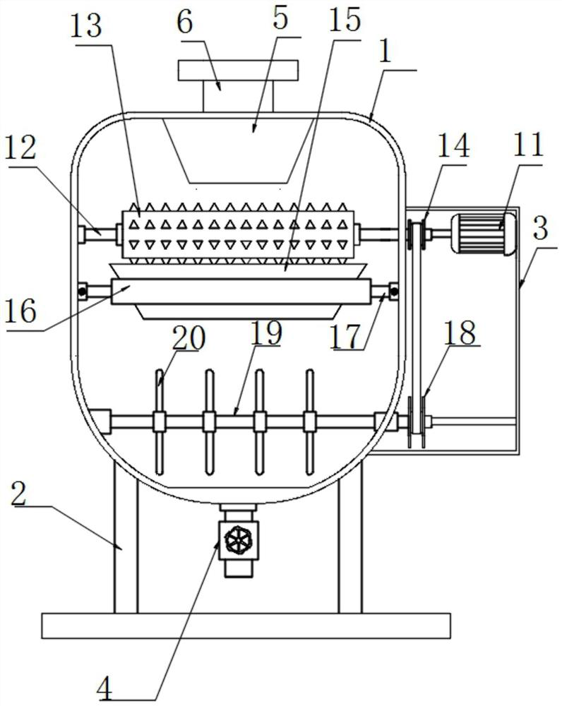
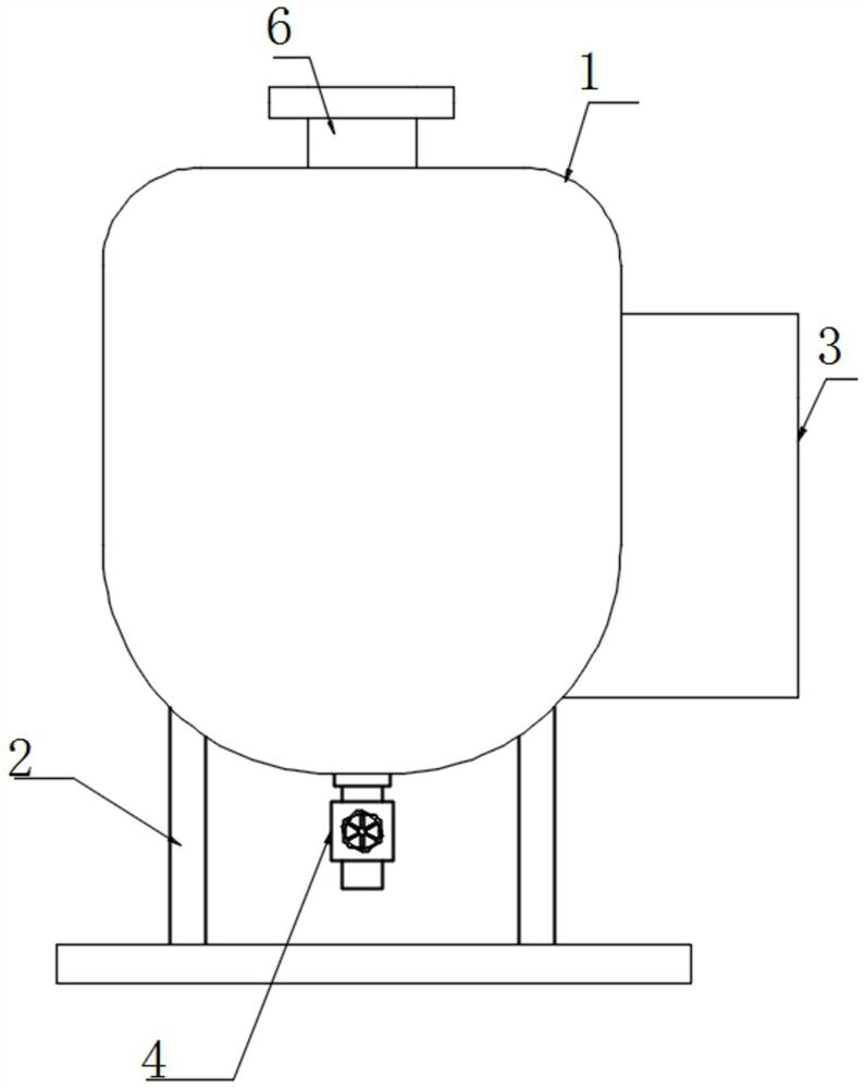
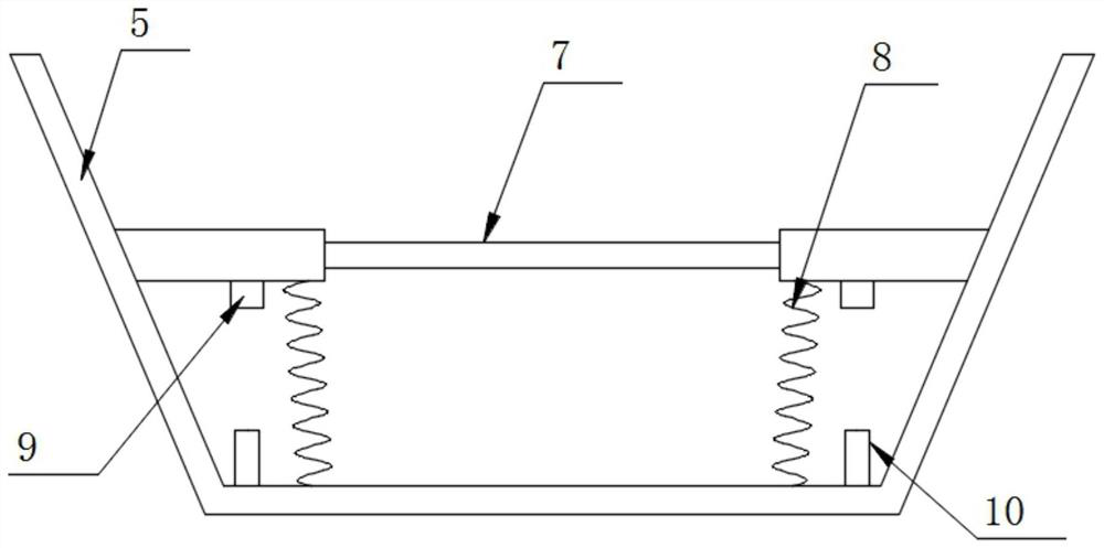
[0024] The embodiment is specifically: start the drive motor 11, pour the raw material into the quantitative box 5 through the feed pipe 6, the raw material falls on the solenoid valve 7, the solenoid valve 7 falls under the action of gravity, and finally the first electrode block 9 and the second electrode block The block 10 is in electrical contact, the valve of the electromagnetic valve 7 is opened, and then the raw material falls between the crushing rollers 13 to be crushed. It makes the amount of crushing uniform each time, the stirring is more sufficient, and the grinding effect is better.

[0025] The working principle of the present invention:

[0026] First close the motor box 4, then start the drive motor 11, pour raw materials into the quantitative box 5 through the feed pipe 6, the raw materials fall on the solenoid valve 7, the solenoid valve 7 falls under the action of gravity, and finally the first electrode block 9 and the second electrode block The two elect...


PUM


Abstract

The invention discloses raw material grinding equipment for ceramic membrane production and particularly relates to the field of ceramic membrane preparation. The raw material grinding equipment comprises an outer box, a base is fixedly installed at the bottom of the outer box, a motor box is fixedly installed on the side face of the outer box, the middle of the bottom face of the outer box fixedly communicates with the motor box, and a feeding pipe fixedly communicates with the top of the outer box; and a quantitative box located below the feeding pipe is fixedly mounted at the top of an inner cavity of the outer box, and an electromagnetic valve is fixedly mounted in the quantitative box. A driving motor is started, raw materials are poured into the quantitative box through the feeding pipe, the raw materials fall onto the electromagnetic valve, the electromagnetic valve falls under the action of gravity, finally, a first electrode block and a second electrode block make electrical contact, a valve gate of the electromagnetic valve is opened, and the electromagnetic valve loses gravity and is driven by the elastic force of a reciprocating spring to restore to the original shape; and quantitative feeding is formed through reciprocating operation in this way, so that the crushing amount each time is uniform, stirring is more sufficient, and the grinding effect is better.

Description

technical field [0001] The invention relates to the technical field of ceramic membrane preparation, and more specifically, the invention relates to a raw material grinding equipment for ceramic membrane production. Background technique [0002] Ceramic film is a means of improving thermal stability of high-energy density batteries. Ceramic coatings are made on the negative electrode sheet and separator of the battery to improve the safety performance of the battery. Grinding uses abrasives coated or pressed on the grinding tool Particles, through the relative movement of the grinding tool and the workpiece under a certain pressure, finish the processing surface. The current raw material grinding equipment for ceramic diaphragm production has poor grinding effect and long grinding time. Therefore, for a ceramic diaphragm production The demand for raw material grinding equipment is growing day by day. [0003] Most of the raw material grinding equipment for the production of...

Claims


Application Information

Patent Timeline
Patent Type & Authority Applications(China)
IPC IPC(8): B02C4/08B02C4/28B02C23/02
CPCB02C4/08B02C4/28B02C4/286
Inventor 万鹏罗琼
Owner 江苏家易欣辰膜科技有限公司
Learn More