
Tool welding clamp jig and method

A welding clip and fixture technology, applied in welding equipment, auxiliary welding equipment, welding/cutting auxiliary equipment, etc., can solve the problems of poor welding quality and low welding efficiency, and achieve the improvement of welding yield and welding efficiency, Quickly realize the effect of positioning and positioning

Pending Publication Date: 2021-11-26
AAC PRECISE MFG TECH CHANGZHOU +1
View PDF0 Cites 0 Cited by
  • Summary
  • Abstract
  • Description
  • Claims
  • Application Information

AI Technical Summary

Problems solved by technology

However, the welding process adopted in the related art has the problems of low welding efficiency and poor welding quality.

Method used


Image

  • Tool welding clamp jig and method
  • Tool welding clamp jig and method
  • Tool welding clamp jig and method

Examples


Embodiment Construction

[0027] The present invention will be further described below with reference to the accompanying drawings and embodiments.

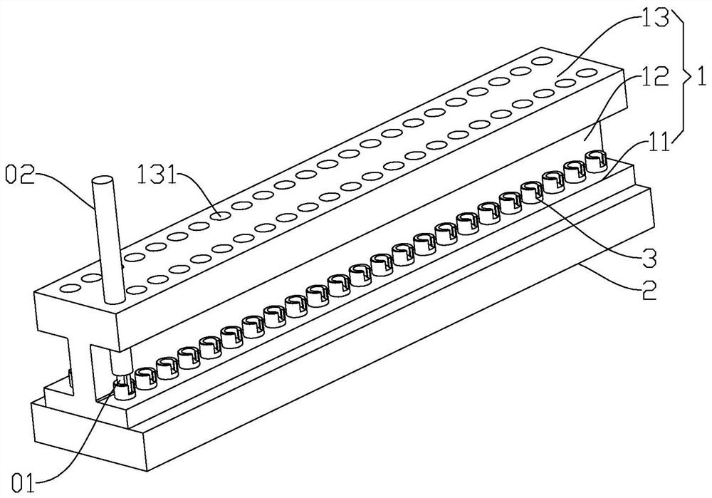
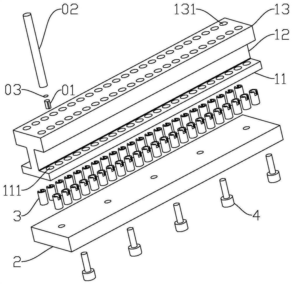
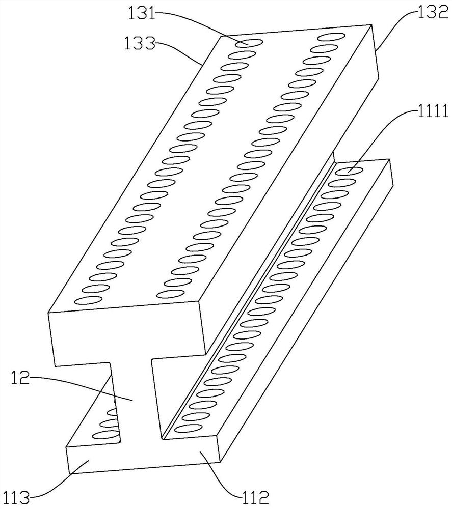
[0028] See Figure 1 to 2 The present invention provides a tool welding fixtures for positioning the welding head 01 and the shank 02, the tool comprises a welding clamp jig fixtures main body 1, and the bottom plate fixtures 2 connected to the body 1 side, and is provided in the fixtures 31 of the pallet main body; wherein the clamp fixture 1 includes a main body connected to the first mounting portion 11 of the base plate 2, the main body portion 2 is provided on the side remote from the first mounting portion 11 and the bottom plate 12 provided in the body the second mounting portion 12 away from the side of the first portion 11 of the mounting portion 13, the first mounting portion 11 is provided for mounting a gantry positioning structure 1113, the pallet 3 for fixing the welding head 01, the second mounting portion 13 defines positioning holes 131 for fi...


PUM


Abstract

The invention provides a tool welding clamp jig and method. The tool welding clamp jig is used for positioning a welding head and a tool bar, and comprises a clamp jig body, a bottom plate connected with one side of the clamp jig body, and a supporting table arranged on the clamp jig body, wherein the clamping jig body comprises a first mounting part connected to the bottom plate, a main body part arranged on the side, away from the bottom plate, of the first mounting part, and a second mounting part arranged on the side, away from the first mounting part, of the main body part; the first mounting part is provided with a positioning structure used for mounting the supporting table; the supporting table is used for fixing a welding head; a positioning hole for fixing the tool bar is formed in the second mounting part; and when the welding head is fixed to the supporting table, the tool bar fixed in the corresponding positioning hole is coaxial with the welding head. According to the tool welding clamp jig and method provided by the invention, the supporting table is mounted on the positioning structure, and the welding head and the tool bar are rapidly positioned and coaxial through the supporting table and the positioning hole, so that the welding centering precision, the welding yield and the welding efficiency are improved; and operation is simple, positioning can be rapidly achieved, and the labor intensity of workers is reduced.

Description

TECHNICAL FIELD [0001] The present invention belongs to the field of manufacturing high-precision tool, particularly to a method of welding and cutting tool clamp fixture. 【Background technique】 [0002] In superhard cutting tool (PCD, CBN, diamond or the like) the manufacturing process, is limited by the high cost of super-hard material, difficult to machine, and a thinner size and other factors, generally hard cutting tool machining using soldering; is welded precision super hard tool indispensable step in the manufacturing process, which directly affect the quality of post-processing tool and the tool productivity. [0003] Substantially related art welding process is divided into: the size of superhard material are required for processing and shank, the shank of superhard materials grinding and welding position, mainly in order to remove the oxide layer; applying solder paste, placement, remove the excess solder paste; then connected together by welding superhard materials an...

Claims


Application Information

Patent Timeline
Patent Type & Authority Applications(China)
IPC IPC(8): B23K3/00B23K3/08B23K1/008B23K37/04
CPCB23K3/00B23K3/08B23K3/087B23K1/008B23K2101/20
Inventor 占方伟马志飞蔡翔都胡飞陈冲
Owner AAC PRECISE MFG TECH CHANGZHOU
Learn More