Upper clamping claw device of textile equipment

A technology of textile equipment and grippers, which is applied in the field of textile automation equipment, can solve problems such as lengthened production cycle, increased equipment load, and low production efficiency, and achieve the effects of large movement range of grippers, precise torque control, and accurate and fast grasping

Pending Publication Date: 2021-11-26
ZHANGJIAGANG YANGTSE SPINNING CO LTD +1
View PDF0 Cites 0 Cited by
  • Summary
  • Abstract
  • Description
  • Claims
  • Application Information

AI Technical Summary

Problems solved by technology

The traditional loading and unloading of two-for-one twisters is manual, which is time-consuming and laborious, and the production efficiency is low. Therefore, some automatic loading and unloading equipment for two-for-one twisters have appeared. During the automatic loading and unloading process, the spindles and bobbins need to be grasped. The shape of the bobbins is different, and the outer diameter varies from 30mm-200mm. Especially the bobbin is tapered. The existing jaws need to be replaced according to different shapes. There are many types of models, which are inconvenient to use and low in efficiency, resulting in longer production cycles. , and the driven load is large, resulting in an increase in the load of the entire device

Method used


Image

  • Upper clamping claw device of textile equipment
  • Upper clamping claw device of textile equipment
  • Upper clamping claw device of textile equipment

Examples


Embodiment 1

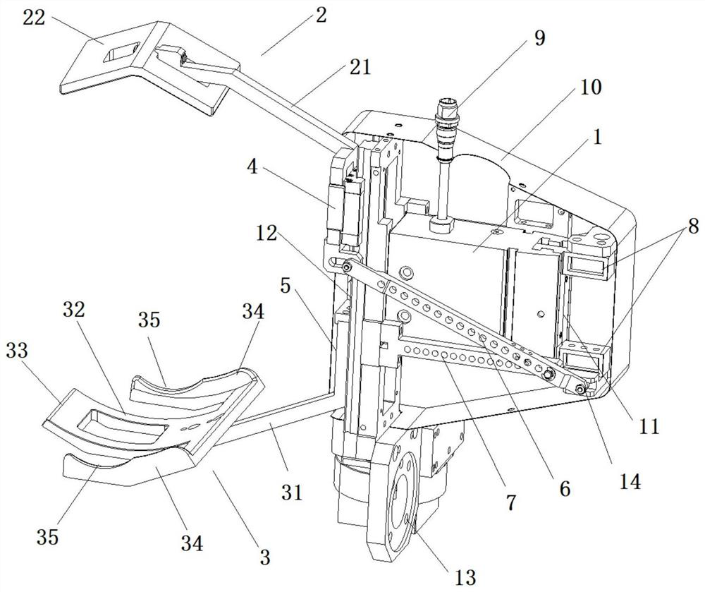
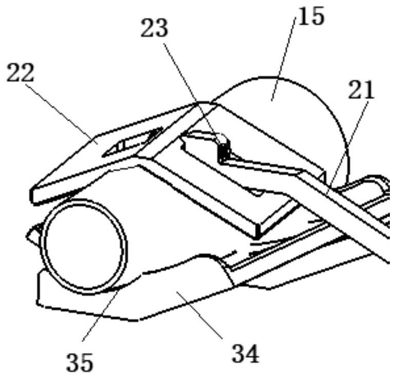
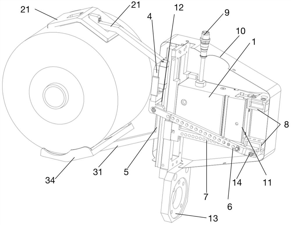
[0018] like Figure 1-Figure 3 The upper jaw device of the textile equipment shown in the present invention includes an upper jaw 2 and a lower jaw 3 that are driven by a torque drive device to move relative to each other. In this embodiment, the upper jaw 2 and the lower jaw 3. Metal materials are preferably used, and hard plastic materials can be used according to the needs of the use environment. The lower clamping jaw 3 includes a lower clamping plate 32 provided with three claws, and the two side claws 34 of the lower clamping plate 32 are symmetrically arranged. The positioning groove 35, the present invention is aimed at the difference between the bobbin 15 and the spindle shape, and the lower clamping plate 32 of the lower three jaws is set, and the upper clamping jaw 2 includes an upper clamping plate 22, and the upper clamping plate 22 is located on the lower clamping plate when clamping 32 between the two side claws 34 and covered on the middle claw 33 of the lower ...

Embodiment 2

[0023] On the basis of Embodiment 1, the torque drive device includes a drive motor, the drive motor preferably adopts a servo motor, which can output torque more accurately, and the upper jaw 2 and the lower jaw 3 pass through the upper slider 4 and the lower jaw respectively. The slider 5 is arranged on the track 12, and the upper slider 4 and the lower slider 5 can slide up and down along the track 12, and the upper slider 4 and the lower slider 5 are respectively connected to the upper link 6 and the lower link. A drive motor, the drive motor drives the upper link 6 and the lower link to drive the upper slider 4 and the lower slider 5 to move up and down, thereby driving the upper jaw 2 and the lower jaw 3 to achieve clamping. In the present invention , the upper link 6 and the lower link move synchronously, and after the movement, the upper and lower sliders 5 are driven to move at the same time. When sliding to both ends, the upper jaw 2 and the lower jaw 3 are separated....

Embodiment 3

[0028] On the basis of the above embodiments, the drive motor is a servo motor, and the servo motor is connected to the cam linkage arranged in the drive chute 11, and the ends of the upper link 6 and the lower link are respectively connected to the The drive slider 8 in the drive chute 11 is connected, and the servo motor drives the drive slider 8 to move up and down through the cam linkage mechanism. It forms a multi-stage connecting rod with the upper and lower struts 31, and produces the largest movement stroke with the smallest volume.

[0029] In this embodiment, the upper link 6 and the lower link are respectively rotatably connected to the drive slider 8 through a cam follower 14, and are rotatably connected to the drive slider 8 through a cam follower 14. Motion trails are smaller.

[0030]In this embodiment, the torque driving device is connected with a signal receiving device 9, and the torque driving device adjusts the torque through the signal received by the sig...


PUM


Abstract

The invention relates to an upper clamping claw device of textile equipment. The device comprises an upper clamping claw and a lower clamping claw which are driven by a torque driving device to move relatively, the lower clamping claw comprises a lower clamping plate provided with three claws, two side claws of the lower clamping plate are symmetrically provided with positioning grooves, the upper clamping claw comprises an upper clamping plate, and the upper clamping plate is located between the two side claws of the lower clamping plate and covers a middle claw of the lower clamping plate during clamping, the design is conducted according to the difference of the shapes of bobbins and spindles, the spindles are fixed mainly through the middle claw and the upper clamping plate when the spindles are grabbed, and due to the fact that the bobbins are conical, the bobbins are easy to slide when the bobbins are grabbed in a claw shape; corresponding positioning grooves are formed in the side claws on the two sides, the two ends of the conical bobbin can be fixed respectively, and after the upper clamping claw covers the bobbin and presses the bobbin, the bobbin is not easy to fall off, and the bobbin is rapidly fixed when grabbed.

Description

technical field [0001] The invention relates to an upper clamping device of textile equipment, which belongs to the technical field of textile automation equipment. Background technique [0002] Textile automation refers to the application of automation technology in the textile industry. The textile industry has many processes, many machines, and high labor intensity. It realizes manual operation and product inspection automation, and implements automatic detection, adjustment, and optimal control of various process parameters. Establishing a production management automation system is a symbol of modern textile production. Textile automation plays an important role in ensuring product quality, improving labor productivity, reducing labor intensity, avoiding environmental pollution, and increasing product designs and colors; after the 1980s, computer group control and computer networks combined with automation management were established one after another; textile automation...

Claims


Application Information

Patent Timeline
Patent Type & Authority Applications(China)
IPC IPC(8): B25J15/08B25J15/02
CPCB25J15/08B25J15/02
Inventor 袁捷唐春晓邓联文仲朝亮黎粒许云鹏倪建兵
Owner ZHANGJIAGANG YANGTSE SPINNING CO LTD
Why Eureka
Try Eureka