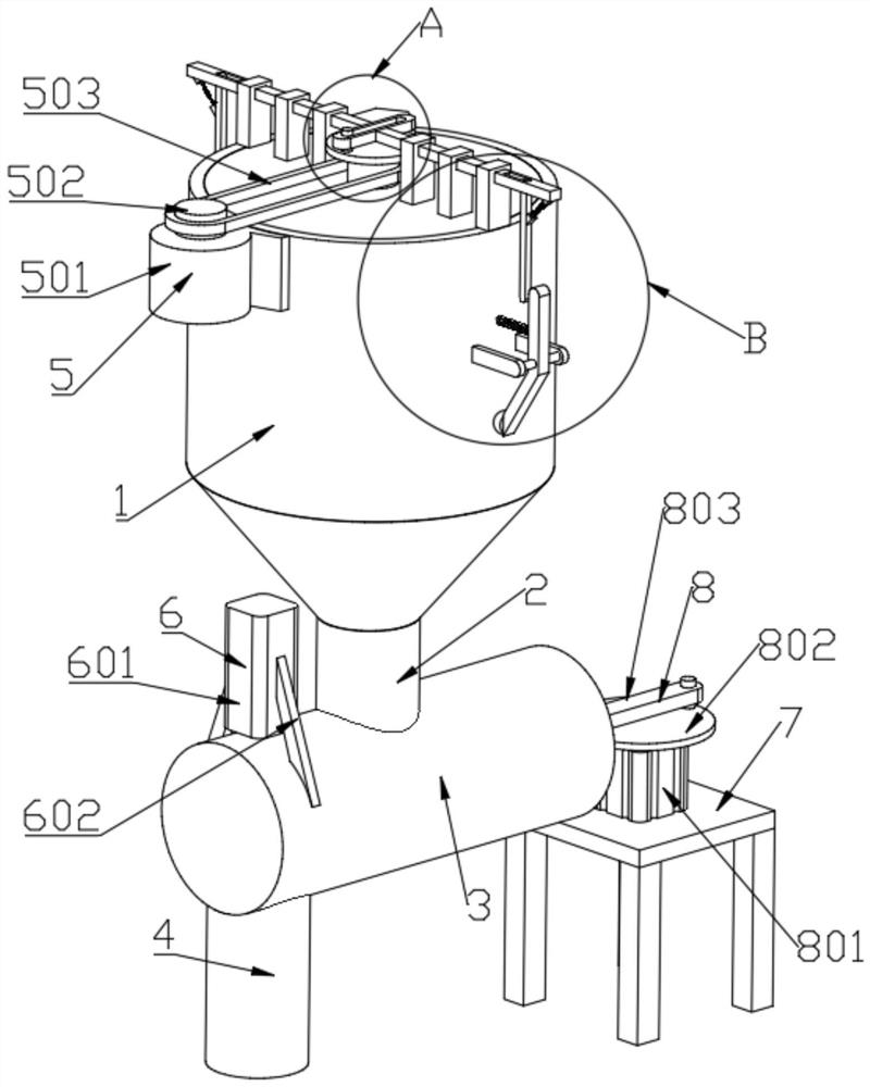
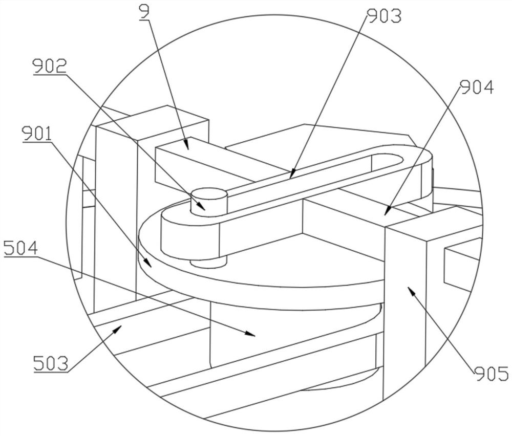
[0029]As a further embodiment of the present invention, the power device 5 includes a first motor 501, a moving wheel 502, a belt 503, and a driven wheel 504, and a first motor 501 fixedly coupled between the storage tank 1, the axis of the first motor 501. The active wheel 502 is connected to the active wheel 502, and the active wheel 502 is connected to the driven wheel 504 by the belt 503, by opening the first motor 501, at this time, the main wheel 502 is rotated, and then the belt 503 is driven from the belt 503 The operation wheel 504 is rotated so that the power supply is provided for the conveying device 11 and the tapping device 9.
[0030] As a further embodiment of the present invention: the conveying device 11 includes a fixing frame 1101, a scorpion 1102, a housing 1103, a rotating shaft 1104, and a scraper 1105, and rotating between the rotating shaft 1104 and the storage tank 1, rotating the shaft 1104 and the driven wheel. The 504 is fixed, and the rotating frame 1104 is fixed to the fixing frame 1101 and the twirle 1102, and the mount 1101 side end is fixedly connected to the squeegee 1105; the lower end of the rotating shaft 1104 is rotated connected to the bearing seat 1103, the bearing seat 1103 and the lower tube 2 between 2, when the work is rotated, the rotation shaft 1104 is rotated by the rotation of the bearing housing 1103, and the fixing frame 1101 and the twinkling 1102 are rotated, and this rotation of the twin 1102 When the phosphite is continuously delivered, the rotation of the fixing frame 1101 is rotated by the scraper 1105, and the inner wall of the cleaning storage tank 1 can be achieved under the action of the blade 1105, thereby reducing phosphorus. Waste of powder.
[0031] As a further embodiment of the present invention: the tap device 9 includes a second disk 901, a slider 902, a moving block, a mobile rod, a restricted seat, a square hole, a second connection block, a first spring, a third connection. Block 909, the lever 910, the rotor rod 911, the second spring 912, the support frame 913, the support shaft 914 and the knock head 915, the limit seat and the storage tank 1 fixed connection, the sliding connection of the limit seat The rod is fixed to the front end of the mobile rod, and the moving block is fixed. The sliding block is slidably connected to the slider 902, and the lower end of the slider 902 is fixedly connected to the second disk 901, and the second disk 901 is fixed between the rotary shaft 1104; A square hole is opened in the end surface, and the square hole is rotated and connected to the line 910. The rear end of the lever 910 is fixedly connected to the third connection block 909. The third connection block 909 is fixedly connected to the first spring, the first spring is far from the third One end of the connecting block 909 is fixedly connected to a second connection block, and the upper end of the second connection block is fixed between the mobile rod; the storage tank 1 is fixed to the support frame 913, and the support frame 913 is fixedly connected to the support shaft 914. The support shaft 914 circumferential surface is rotated and connected to the rotating rod 911, the rear end fixation of the rotary rod 911 and the second spring 912, the second spring 912 is fixed to the storage tank 1, and when working, with the rotation The rotation of 1104 vaps the second circular disk for rotation, at this time, the moving block is moved under the action of the slider 902, which in turn has a movement sliding in the limit seat, and the movement of the mobile rod When moving outward, at this time, the lever 910 can be rotated in a square hole under the action of the rotating lever 911, and when the lever 910 passes through the rotating rod 911, at this time at the first spring, the second connecting block, and the third connection. Under the action of block 909, the lever 910 can be reset to facilitate the dial rotor rod 911, when the movement is moved inward, when the mobile rod contacts the rotating rod 911, at this time, at this time, at this time, at this time the support frame 913 and the support shaft 914. Under the action, the rotating lever 911 can be rotated, when the rotational rod 911 is disengaged from the lever 910, at this time, the rotating rod 911 is rotated in the opposite direction, so that the knocking ball is moved. Thus, the purpose of tapping the storage tank 1 can be achieved under the action of the knocking head 915, so that the tank 1 is falling in the tank 1.
[0032] As a further embodiment of the present invention: the pushing device 8 includes a second motor 801, a first disc 802, a link 803, a push block 804, a first fixing shaft 805, and a first connecting block 806, push block 804. Slide between the fixing cartridge 3, the push block 804 side ends fixed to the first connecting block 806, the first connecting block 806 side is rotated to connect the link 803, and the link 803 is away from one end of the first connection block 806. The rotation is connected to the first fixing shaft 805, and the first fixing shaft 805 is fixedly connected to the first disk 802, and the lower end of the first disk 802 is fixed to the second motor 801 out of the axis, and the second motor 801 is fixedly connected to the base. 7. When working, by turning on the second motor 801, the first disk 802 is rotated, and the first fixed shaft 805 is moved, and the action of the link 803 and the first connection block 806 will be moved. The push block 804 can be moved within the fixing tube 3 so that the phosphite in the fixing cylinder 3 can be pushed into the discharge tube 4.
[0033] As a further embodiment of the present invention, the lower pressure device 6 includes a cylinder 601, a fixing rod 602, and an extrusion block 603, and a fixed rod 602 is fixed between the fixed barrel 3, and the rear end of the fixed bar 602 is fixedly connected to the cylinder 601. When the lower end of the cylinder 601 is fixed to the pressing block 603, when operating, the cum tank 601 is turned on, and the pressing block 603 is moved, so that the phosphite in the lower tube 2 can be moved, so that it can be achieved. Extrusion of phosphite.
[0034] As a further embodiment of the present invention, the sealing device 12 includes a connecting frame 1201, a second fixing shaft 1202, a sealing plate 1203, and a torsion spring 1204, and a fixed connection between the connecting frame 1201 and the discharge tube 4, and the connecting frame 1201 is rotated The second fixing shaft 1202 is connected, and the second fixing shaft 1202 circumferential surface is fixedly coupled to the torsion spring 1204 and the sealing plate 1203, and the torsion spring 1204 is fixed between the connecting spring 1201, and when the squeezing block 603 is phosphite Squeeze, so that the sealing plate 1203 can be rotated in the action of the second fixing shaft 1202, so that the phosphorus in the lower tube 2 can be dropped down, and the phosphorus in the lower tube 2 fell, At this time, the sealing plate 1203 can be reset under the action of the torsion spring 1204, so that the sealing effect can be achieved.
[0035] The working principle of the present invention is:
[0036] When the present invention is used, weigh the instrument in the storage tank 1, when a phosphorus is required, by opening the first motor 501, the main wheel 502 is rotated, and the driven wheel is driven under the action of the belt 503. 504 rotation, the driven wheel 504 rotates, at this time, the rotating shaft 1104 is rotated under the action of the bearing housing 1103, and the fixing frame 1101 and the twinkling 1102 rotate, and the phosphorus can be constantly improving with the rotation of the twezy 1102. Down, the rotation of the fixing frame 1101 is rotated, and the purpose of cleaning the inner wall of the storage tank 1 can be achieved under the action of the scraper 1105, thereby reducing waste of phosphite while reducing the waste of phosphite while The rotation of the shaft 1104 is rotated with a second circumferential disk, and the moving block is moved in the action of the slide lever 902, which in turn is moved to slide in the restricted seat, and when the movement of the mobile rod When the rod moves outward, at this time, the lever 910 can be rotated in the square hole, and when the lever 910 passes through the rotating rod 911, at this time the first spring, the second connection block and the third Under the action of the connecting block 909, the lever 910 can be reset to facilitate the dial rotor rod 911, when the movement is moved inward, when the mobile rod is in contact with the rotating rod 911, at this time, at this time, at this time, at this time, at this time, at this time, at this time, at this time, at this time, at this time, at this time, at this time in the support frame 913 and the support shaft 914. Under the action, the rotating lever 911 can be rotated, when the rotational rod 911 is disengaged from the lever 910, at this time, the rotating rod 911 is rotated in the opposite direction, so that the tap ball is moved. In this way, the purpose of tapping the storage tank 1 can be achieved under the action of the knocking head 915 to facilitate the falling tank 1, and when a weight of the phosphat, the first motor 501 is closed at this time. The second motor 801 is then turned on. At this time, the first disk 802 is rotated, and the first fixed shaft 805 is moved, and the push block can be made under the action of the link 803 and the first connecting block 806. 804 moves within the fixing cylinder 3, so that the phosphorus powder in the fixing cylinder 3 can be pushed into the lower tube 2, and when the phosphite falls into the discharge tube 4, then open the cylinder 601, it will be moved. The squeezing block 603 is moved so that the squeezing block 603 is extruded with the phosphite, and as the extrusion block 603 is extruded with the phosphite, the sealing plate 1203 can be carried out under the action of the second fixing shaft 1202. Turning, so that the phosphorus powder in the lower tube 2 can be removed, and when the phosphorus in the lower tube 2 is finished, the sealing plate 1203 can be reset under the action of the torsion spring 1204, so that it can be sealed. Effect.