Filling equipment for adhesive production
A filling equipment and adhesive technology, applied in the field of filling equipment for adhesive production, can solve the problems of error, manual secondary filling, low production efficiency, etc.
- Summary
- Abstract
- Description
- Claims
- Application Information
AI Technical Summary
Problems solved by technology
Method used
Image
Examples
Embodiment 1
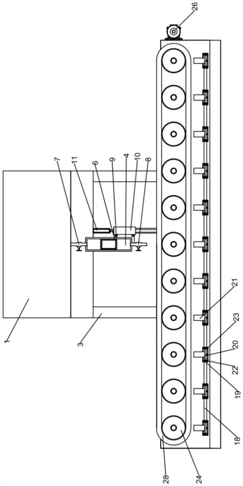
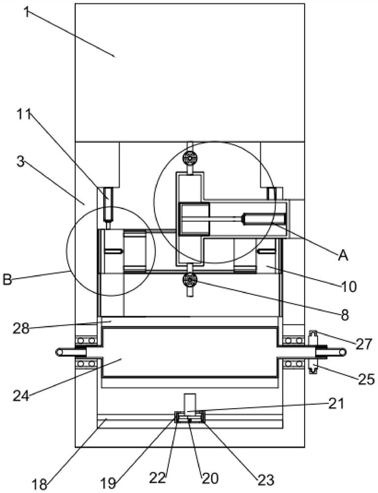
[0032] Embodiment 1: By opening the transfer valve 7 and closing the unloading valve, the contraction of the transfer hydraulic cylinder 5 drives the concave push plate 6 on the push end of the transfer hydraulic cylinder 5, and the movement of the concave push plate 6 achieves the storage tank The liquid in 1 is diverted to the inner side of the transfer hydraulic cylinder 5, and then the transfer valve 7 is closed, and the unloading valve is opened, and then the transfer hydraulic cylinder 5 is extended, and the concave push plate 6 on it is respectively pushed, and the T-shaped The glue in the drainage tube 4 is squeezed out, and the glue is transferred and loaded through the T-shaped drainage tube 4, so as to ensure that the amount of glue squeezed out each time is quantitative.
[0033] According to attached Figure 1-5 It can be concluded that the lifting and positioning structure includes: lifting L-shaped plate 10, a pair of lifting and correcting hydraulic push rods 1...
Embodiment 2
[0035] Embodiment 2: Through a pair of lifting and correcting hydraulic push rods 11 telescopic, push a pair of lifting and correcting hydraulic push rods 11 to push the lifting L-shaped plate 10 on the end, and carry out the glue bottle on the concave transporter 2 through the lifting and lowering L-shaped plate 10. Limiting in the horizontal direction, through the cooperation of a pair of lifting sliders 13 and a pair of lifting slides 12, the lifting L-shaped plate 10 is lifted in the vertical direction, and simultaneously through a pair of lifting sliders 13 and a pair of lifting slides 12, so as to achieve the limit of the glue bottle, and at the same time, the two pairs of extrusion hydraulic push rods 14 on the lifting L-shaped plate 10 are stretched and retracted, respectively driving the two pairs of extrusion hydraulic push rods 14 to push the correction plate 15 on the end, Through a pair of straightening plates 15, the glue bottle is squeezed and fixed in the horizo...
Embodiment 3
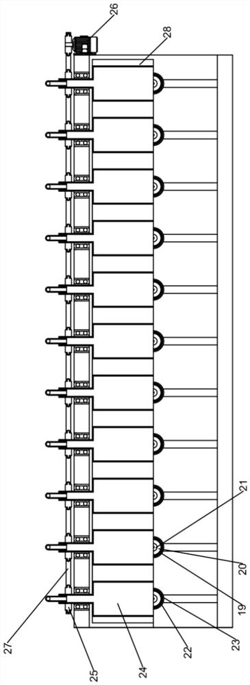
[0038] Embodiment 3: Through the vibration of several sonic vibrators 21, the liquid in the concave transporter 2 is driven to vibrate, and some parts in the transport structure are cleaned by sonic waves through the vibrating water, and several sonic vibrators 21 are respectively used to drive their Several cleaning rings 20 on the top vibrate and rotate in several concave ring blocks 19 respectively, and at the same time through the cooperation of several vibration shafts 22 and several vibration flexible wheels 23 in several concave ring blocks 19, the vibration is converted It is the rotation in the horizontal direction of several vibrating shafts 22 and several vibrating flexible wheels 23 and the elastic deformation of several vibrating flexible wheels 23 .
[0039] According to attached Figure 1-5 It can be concluded that the transportation structure includes: several transportation rollers 24, several transportation sprockets 25, transportation driving machine 26, tra...
PUM
 Abstract
Description
Claims
Application Information
 - R&D
- Intellectual Property
- Life Sciences
- Materials
- Tech Scout
- Unparalleled Data Quality
- Higher Quality Content
- 60% Fewer Hallucinations
Browse by: Latest US Patents, China's latest patents, Technical Efficacy Thesaurus, Application Domain, Technology Topic, Popular Technical Reports.
© 2025 PatSnap. All rights reserved.Legal|Privacy policy|Modern Slavery Act Transparency Statement|Sitemap|About US| Contact US: help@patsnap.com


