Pouring device for cast-in-place box girder of spliced wide bridge

A cast-in-place and box girder technology, which is applied in bridges, bridge construction, erection/assembly of bridges, etc., can solve the problems of high labor intensity, time-consuming and laborious, etc., and achieve the effects of reducing labor intensity, ensuring stability, and facilitating cleaning

Pending Publication Date: 2021-11-26
CHINA FIRST HIGHWAY ENG +1
View PDF0 Cites 0 Cited by
  • Summary
  • Abstract
  • Description
  • Claims
  • Application Information

AI Technical Summary

Problems solved by technology

There are also air vents that are set to discharge the air in the formwork (or pipes) during pouring (or pipe grouting), and must be sealed at the

Method used


Image

  • Pouring device for cast-in-place box girder of spliced wide bridge
  • Pouring device for cast-in-place box girder of spliced wide bridge
  • Pouring device for cast-in-place box girder of spliced wide bridge

Examples


Embodiment 1

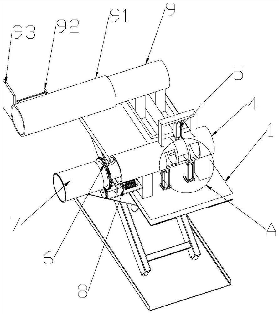
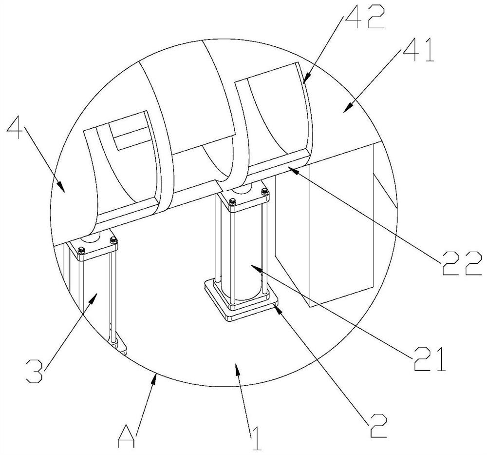
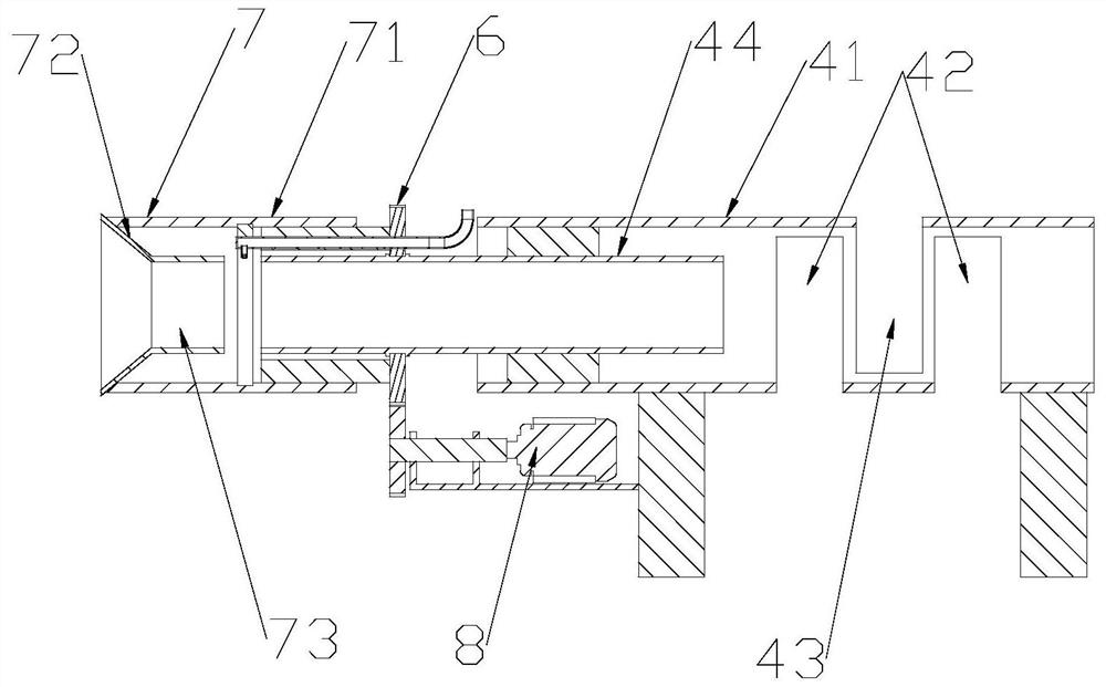
[0026] A pouring device for cast-in-place box girders of Pinkuan Bridge, the pouring device includes a lifting platform 1, such as figure 1 , figure 2 As shown, universal wheels are provided under the lifting platform 1, a first clamping part 2 is provided on the lifting platform 1, a second clamping part 3 is provided on the lifting platform 1, and a fixing part 4 is provided on the lifting platform 1. The fixing part 4 is provided with a third clamping part 5, and the fixing part 4 is provided with a cutting part 6 for rotation, and the cutting part 6 is provided with a material guide part 7, and the material guide part 7 is connected with the cutting part 6 in rotation, and the guide material The part 7 can also be firmly connected with the cutting part 6, and the driving part 8 is arranged on the lifting table 1.

[0027] The first clamping member 2 includes a hydraulic cylinder 21, such as figure 2 As shown, the output shaft of the hydraulic cylinder 21 is tightly con...

Embodiment 2

[0033] Embodiment 2 further includes a grouting part 9 on the basis of Embodiment 1.

[0034] Grouting part 9 comprises telescoping tube 91, as figure 1 As shown, the telescopic tube 91 is slidingly connected with the lifting platform 1, the telescopic tube 91 is provided with a telescopic cylinder 92, the output shaft of the telescopic cylinder 92 is fastened to a scraper 93, and the telescopic tube 91 is connected with the grouting machine.

[0035] When in use, move the lifting platform 1 so that the trumpet tube 72 is aligned with the concave hole at the end of the box girder, and push the transfer so that the concave hole steel bar is inserted into the horn hole 72 and the guide tube 44, and the outer tube is inserted into the end hole of the box beam. The hydraulic cylinders on the holding part 2, the second holding part 3 and the third holding part 5 push the splint 22 to clamp the steel bar group, start the motor 81 and the gas cutting machine, and the cutting part 6 d...


PUM


Abstract

The invention discloses a pouring device for a cast-in-place box girder of a spliced wide bridge , which comprises a lifting platform, a first clamping piece is arranged on the lifting platform, a second clamping piece is arranged on the lifting platform, a fixing piece is arranged on the lifting platform, a third clamping piece is arranged on the fixing piece, a cutting piece is rotationally arranged on the fixing piece, and a material guiding piece is arranged on the cutting piece. A driving part is arranged on the lifting table, and a grouting part is arranged on the lifting table in a sliding mode. According to the pouring device, the material guiding piece penetrates into the concave hole in the end of the box girder to be matched with the rotating cutting piece, a steel bar group in the concave hole is cut off through gas cutting, the cutting efficiency is high, the labor intensity of workers is reduced. Meanwhile, the length of the cut steel bar is smaller than the depth of the hole, later grouting and trowelling are facilitated, the steel bar is effectively clamped by the clamping piece during cutting. The cutting scatter is prevented, and the subsequent cutting cleaning is faciliated. The device is provided with the grouting piece, so that the holes are efficiently grouted and flattened, and the stability of the box girder structure is guaranteed.

Description

technical field [0001] The invention relates to a pouring device, in particular to a pouring device for a cast-in-place box girder of a Pinkuan Bridge. Background technique [0002] The current bridge construction includes two parts: pier column pouring and box girder erection. The box girder and the erection area between two adjacent pier columns are set in one-to-one correspondence. The box girder erection is to erect a single box girder between two adjacent pier columns. process in between. When the box girder is being poured, due to the hydration heat reaction of the concrete or the sudden change of the external temperature, the excessive temperature difference between the inside and the outside will cause damage to the box girder, so vent holes are set. There are also air vents that are set to discharge the air in the formwork (or pipes) during pouring (or pipe grouting), and must be sealed at the end, but there are steel bars in the vent holes, which need to be cut be...

Claims


Application Information

Patent Timeline
IPC IPC(8): E01D21/00E01D2/04B21F11/00
CPCE01D21/00E01D2/04B21F11/00
Inventor 谭小磊黄超孟雷尤爰智汪余川程杨明
Owner CHINA FIRST HIGHWAY ENG
Why Eureka
Try Eureka