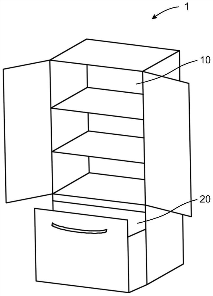
Drying assembly and refrigeration equipment
A drying and component technology, used in refrigerators, refrigeration components, refrigeration and liquefaction, etc., can solve the problems of unbalanced distribution and unbalanced cooling effect, and achieve the effect of balanced cooling effect, low cost and simple structure
- Summary
- Abstract
- Description
- Claims
- Application Information
AI Technical Summary
Problems solved by technology
Method used
Image

Examples
Embodiment Construction
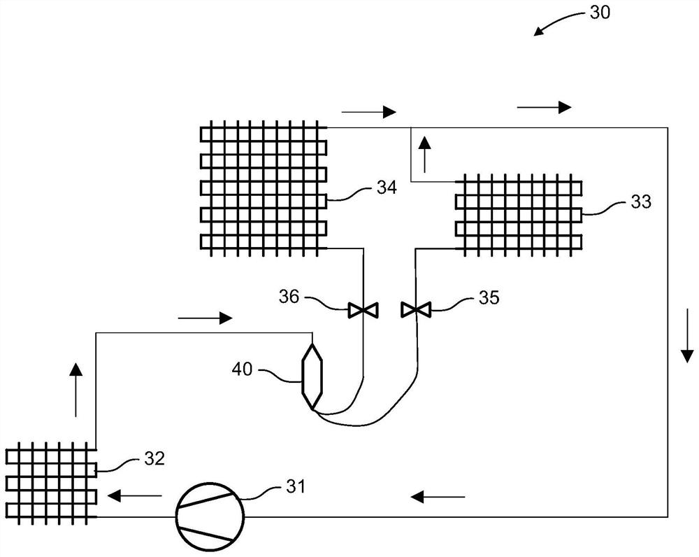
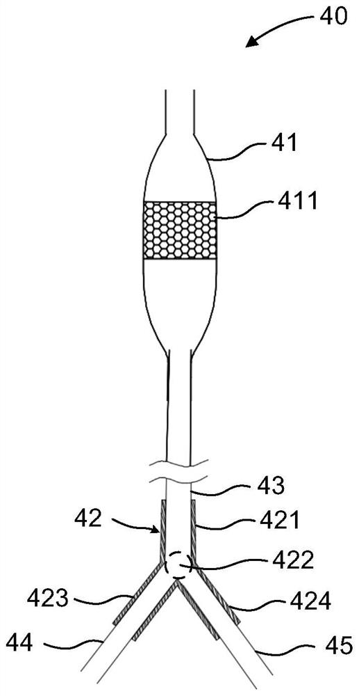
[0031] In the existing refrigeration equipment, when the refrigerant enters multiple capillaries after being filtered by the drying tube, the distribution in each capillary is often very unbalanced. Some capillaries are dominated by liquid-phase refrigerants, and some capillaries are dominated by gas-phase refrigerants. Mainly, resulting in unbalanced cooling effect of each compartment in the refrigeration equipment.
[0032] Different from the prior art, in the technical solution provided by the embodiment of the present invention, the drying assembly includes: a drying pipe, which is suitable for drying the refrigerant; a flow divider, which communicates with the drying pipe and divides the refrigerant from the drying pipe so that The refrigerant flows into at least two output branches respectively in the state of liquid phase, gas phase or gas-liquid two-phase.
[0033] Compared with the prior art, the drying assembly provided by the embodiment of the present invention can ...
PUM
 Abstract
Description
Claims
Application Information
PatSnap Eureka turns technology decisions into work you can execute. Powered by our Innovation Knowledge Graph, it runs expert workflows across engineering, life sciences, materials and intellectual property. Get your review-ready output in minutes.


