
Wall thickness detection system and method and storage medium

A detection system and detection method technology, which is applied to measuring devices, instruments, and the use of ultrasonic/sonic/infrasonic waves, etc., can solve the problems of high cost, low detection efficiency, and high risk of ultrasonic probes and high-temperature couplants, and improve work stability. performance and reliability, improving efficiency and reliability, and improving detection accuracy

Pending Publication Date: 2021-11-26
ZHUHAI WINBASE INT CHEM TANK TERMINAL CO LTD
View PDF0 Cites 0 Cited by
  • Summary
  • Abstract
  • Description
  • Claims
  • Application Information

AI Technical Summary

Problems solved by technology

In view of the problem of wall thickness thinning caused by localized corrosion of high-temperature pipelines, the main preventive measure at present is to use high-temperature thickness gauges to regularly measure the thickness of the pipeline at fixed points. Although this method can reduce the occurrence of accidents to a certain extent, it cannot fundamentally Overcoming sudden and occasional characteristics of pipe wall thickness reduction
Due to the large number of pipelines working on the equipment site, the wall thickness detection generally adopts a proportional sampling method, which is difficult to ensure full coverage of dangerous parts, multi-point detection cannot be achieved, and the detection efficiency is low; at the same time, ultrasonic probes used in high-temperature detection scenarios The high-temperature couplant is expensive, inconvenient to disassemble and assemble, close contact is required when measuring the wall thickness of high-temperature pipes, the working conditions are poor, and the risk is high

Method used


Image

  • Wall thickness detection system and method and storage medium
  • Wall thickness detection system and method and storage medium
  • Wall thickness detection system and method and storage medium

Examples


Embodiment Construction

[0033] This part will describe the specific embodiment of the present invention in detail, and the preferred embodiment of the present invention is shown in the accompanying drawings. Each technical feature and overall technical solution of the invention, but it should not be understood as a limitation on the protection scope of the present invention.

[0034] In the description of the present invention, it should be understood that the orientation descriptions, such as up, down, front, back, left, right, etc. indicated orientations or positional relationships are based on the orientations or positional relationships shown in the drawings, and are only In order to facilitate the description of the present invention and simplify the description, it does not indicate or imply that the device or element referred to must have a specific orientation, be constructed and operated in a specific orientation, and thus should not be construed as limiting the present invention.

[0035] I...


PUM


Abstract

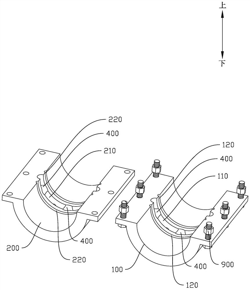
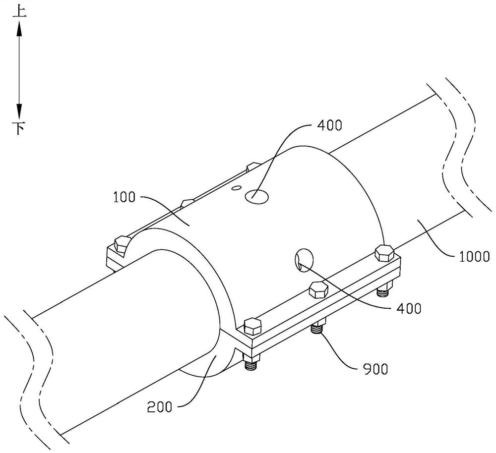
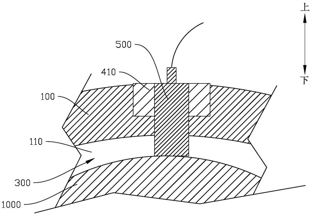
The invention relates to a pipeline detection technology, and discloses a wall thickness detection system and method and a storage medium. The system comprises a first clamping part provided with a first groove, a second clamping part provided with a second groove, a positioning hole, ultrasonic probes, a temperature measuring module, an ultrasonic detector, a circulating pump and a cooling water tank, wherein a cooling channel is formed by the first groove, the second groove and the surface of the pipeline. By means of detachable connection of the first clamping part and the second clamping part, mounting or dismounting can be facilitated, and convenience is improved; cooling liquid injected into the cooling channel can be used as a coupling agent and is used for cooling the ultrasonic probes; a plurality of ultrasonic probes are distributed on the cooling channel to realize multi-point detection; the temperature measuring module monitors the working environment temperature of the ultrasonic probes and is matched with the circulating pump to adjust the flow speed of the cooling liquid in the cooling channel so as to adjust the temperature of the cooling liquid, so that the ultrasonic probe works in a proper temperature range, and the working stability, reliability and detection precision of the ultrasonic probe are effectively improved.

Description

technical field [0001] The invention relates to pipeline detection technology, in particular to a wall thickness detection system, method and storage medium. Background technique [0002] High-temperature pipelines are widely used in petrochemical, coal chemical, nuclear power and other fields. Due to long-term high-temperature and high-pressure working environments, pipelines have failure risks such as wall thickness reduction, corrosion cracking, and perforation leakage. In view of the problem of wall thickness thinning caused by localized corrosion of high-temperature pipelines, the main preventive measure at present is to use high-temperature thickness gauges to regularly measure the thickness of the pipeline at fixed points. Although this method can reduce the occurrence of accidents to a certain extent, it cannot fundamentally Overcome the sudden and occasional characteristics of pipe wall thickness reduction. Due to the large number of pipelines working on the equipm...

Claims


Application Information

Patent Timeline
Patent Type & Authority Applications(China)
IPC IPC(8): G01B17/02
CPCG01B17/02
Inventor 陈子红张贤
Owner ZHUHAI WINBASE INT CHEM TANK TERMINAL CO LTD
Learn More