Overload protection device for electricity meter
An overload protection and electricity meter technology, applied in measuring devices, measuring electrical variables, instruments, etc., can solve the problems of difficult heat dissipation, poor dustproof performance of the shell, affecting the protection of electricity meters, etc., and achieve the effect of preventing accumulation
- Summary
- Abstract
- Description
- Claims
- Application Information
AI Technical Summary
Problems solved by technology
Method used
Image

Examples
Embodiment 1
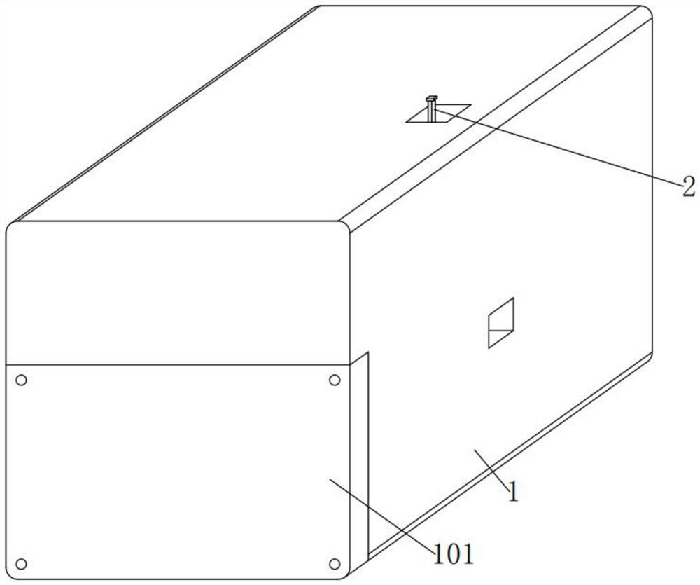
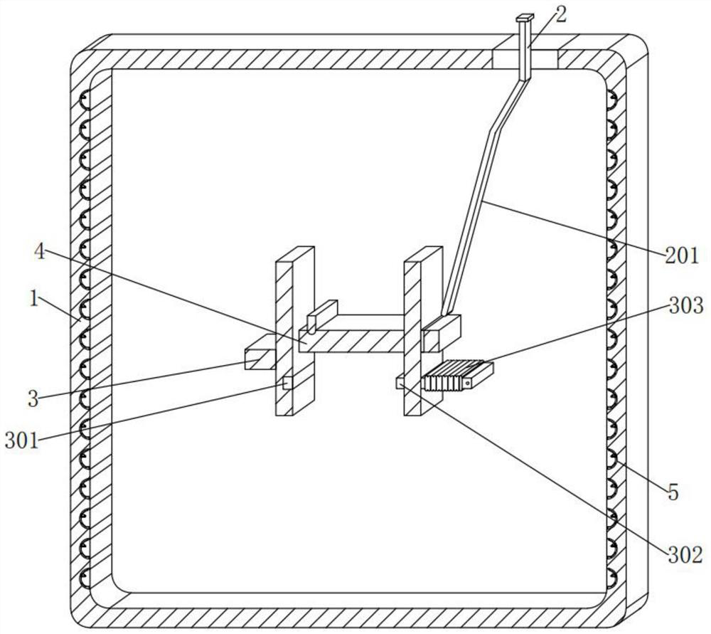
[0045] see Figure 1-3 In an embodiment of the present invention, an overload protection device for an electric meter includes a housing 1, a sealing cover 101, a straight shaft 2, a lever 201, a permanent magnet 3, a first electrode piece 301, a second electrode piece 302, Conductive coil 303 and chute 4,
[0046] The dust-proof assembly 5, the internal position of the longitudinal side inner wall of the housing 1 is arranged vertically in an up-and-down vertical direction, and several dust-proof assemblies 5 that can prevent dust from accumulating are embedded.
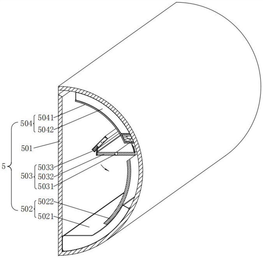
[0047] Each group of dustproof components 5 includes a dust collecting case 501, a deformable component 502 that can deform to promote dust prevention after dust enters, a movable component 503 that can move to promote dust prevention after dust enters, and can prevent collection. Anti-spill assembly 504 for dust spillage.
[0048] In the embodiment of the present invention, the dust collecting case 501, each dust...
Embodiment 2
[0052] see Figure 3-Figure 7 Compared with Embodiment 1, this embodiment of the present invention differs in that: deformation components 502 , each set of deformation components 502 includes a lower air bag 5021 and a limiting plate 5022 .
[0053] In the embodiment of the present invention, the lower airbag 5021 is embedded with the lower airbag 5021 between the inner bottom of each dust collecting case 501 and the right end. The outer surfaces of the left side and the bottom side of each are attached to the inner wall of each dust collecting case 501;
[0054] Here, the lower airbag 5021 and its appearance are left and right arc-shaped, which is designed to use the principle of negative pressure to press the lower airbag 5021 to deform after the dust falls into the dust collecting case 501, so as to trigger the subsequent activities of the movable components 503;
[0055] Limiting plate 5022, the position between the inner right end of each dust collecting case 501 and th...
Embodiment 3
[0067] see image 3 , Figure 8-9 Compared with Embodiment 1, the difference between this embodiment of the present invention lies in: anti-overflow components 504 , and each set of anti-overflow components 504 includes a fixing plate 5041 and an upper airbag 5042 .
[0068] In the embodiment of the present invention, the fixed plate 5041 is fixedly installed from the inner right end of each dust collection case 501 to the top position, and the appearance of each fixed plate 5041 is in the shape of an inverted letter F in a longitudinal section. , between the right outer wall of each fixing plate 5041 and the inner wall of each dust collecting case 501, a first cavity and a second cavity are sequentially opened from bottom to top, and an outlet is opened on the top of the left end of the second cavity, The material of each fixing plate 5041 is copper;
[0069]On the upper air bag 5042, an upper air bag 5042 is embedded between the right outer wall of each fixing plate 5041 d...
PUM
 Abstract
Description
Claims
Application Information
 - R&D
- Intellectual Property
- Life Sciences
- Materials
- Tech Scout
- Unparalleled Data Quality
- Higher Quality Content
- 60% Fewer Hallucinations
Browse by: Latest US Patents, China's latest patents, Technical Efficacy Thesaurus, Application Domain, Technology Topic, Popular Technical Reports.
© 2025 PatSnap. All rights reserved.Legal|Privacy policy|Modern Slavery Act Transparency Statement|Sitemap|About US| Contact US: help@patsnap.com