Heat dissipation device

A heat dissipation device and heat dissipation fin group technology, applied in indirect heat exchangers, lighting and heating equipment, cooling/ventilation/heating transformation, etc., can solve problems such as difficulty in heat dissipation, and achieve large effective contact area and expanded condensation area Effect

Pending Publication Date: 2021-11-26
SHANGHAI XUNKE ENERGY SAVING TECH CO LTD
View PDF0 Cites 1 Cited by
  • Summary
  • Abstract
  • Description
  • Claims
  • Application Information

AI Technical Summary

Problems solved by technology

[0003] In order to solve the problem of difficult heat dissipation of current power electronic equipment, this invention proposes a heat dissipation device, which can overcome the technical defects of vapor chambers and heat pipes, and has the advantages of large heat dissipation capacity, high efficiency, small size, and convenient use. The advantages of simple, reliable and low-cost air-cooled heat dissipation devices provide more advanced solutions for the increasingly severe heat dissipation problems of power electronic products

Method used


Image

  • Heat dissipation device
  • Heat dissipation device
  • Heat dissipation device

Examples


no. 1 example

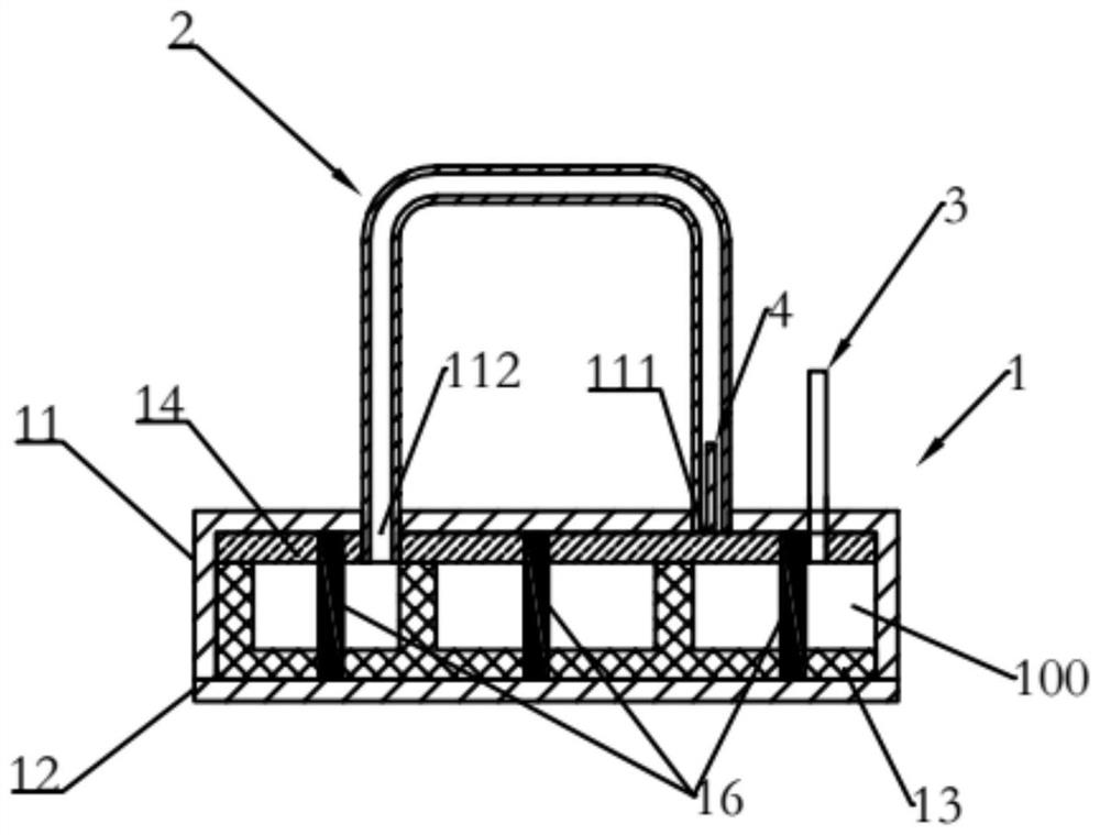
[0037] see image 3 , is a cross-sectional view of the second embodiment of a heat dissipation device of the present invention. As shown in the figure, the chamber 100 has a first capillary tissue 13 , a second capillary tissue 14 , a third capillary tissue 15 and a support body 16 . The third capillary tissue 15 contacts or connects with the first capillary tissue 13 and the second capillary tissue 14 respectively, so as to realize the indirect contact or connection between the first capillary tissue 13 and the second capillary tissue 14 . The third capillary structure 15 can be selected as any one or a composite structure of wire mesh, metal foam, metal felt, fiber bundle, and powder porous structure. In order to increase the condensation area and strengthen the heat exchange effect, the outer surface of the upper cover 11 of this embodiment is provided with a second cooling fin group 6 (shown in the figure), but it is not limited, and it can also be installed on the outer ...


PUM


Abstract

The invention discloses a heat dissipation device. The heat dissipation device comprises a shell, pipe bodies and a filling pipe. The shell comprises a cover plate and a bottom plate, and the cover plate and the bottom plate are combined to form a hollow cavity. A first capillary structure and a second capillary structure are arranged in the cavity. The first capillary structure and the second capillary structure directly or indirectly contact with each other or are connected with each other locally. The cover plate is provided with a plurality of first open holes and second open holes with the same number as the first open holes, the first open holes are covered with second capillary structure, and the second open holes are not provided with the second capillary structure, so that the second open holes are communicated with the cavity. The number of the pipe bodies is equal to that of the first open holes, and each pipe body is provided with two end openings which are respectively communicated with one first open hole and one second open hole. The heat dissipation device has the advantages of being large in heat dissipation capacity, high in heat dissipation efficiency, simple and reliable.

Description

technical field [0001] The invention belongs to the technical field of heat dissipation, and relates to a heat dissipation device for power electronic equipment. Background technique [0002] Air-cooled heat dissipation devices are widely used in the field of power electronics heat dissipation due to their simplicity, reliability, and low price. However, with the rapid development of industries such as big data, AI, and the Internet of Things, the power consumption of hardware integrated circuits is increasing, and the heat generation and heat flux density are also increasing. The heat dissipation capacity of traditional air-cooled heat dissipation devices such as heat pipe radiators and vapor chambers is increasingly difficult to meet the demand. The heat transfer capacity of the heat pipe is small, and the effective contact area with the heat source is small. The effective contact area between the vapor chamber and the heat source is large, but its condensation area is d...

Claims


Application Information

Patent Timeline
Patent Type & Authority Applications(China)
IPC IPC(8): H05K7/20F28D15/02F28D15/04
CPCH05K7/20336F28D15/0275F28D15/04
Inventor 赵秀红牟永斌
Owner SHANGHAI XUNKE ENERGY SAVING TECH CO LTD
Why Eureka
Try Eureka