Braking system for fan blade rotating shaft of wind generating set

A technology of wind turbines and braking systems, which is applied in the control of wind turbines, wind turbines, and wind power generation. It can solve problems such as fire hazards, shutdown maintenance hazards, and brakes that cannot be manually braked, achieving the effect of simple structure.

Active Publication Date: 2021-11-30
JIAXING NANYANG POLYTECHNIC INST
View PDF14 Cites 1 Cited by
  • Summary
  • Abstract
  • Description
  • Claims
  • Application Information

AI Technical Summary

Problems solved by technology

[0003] The first object of the present invention is to provide a wind turbine blade rotor shaft brake system that can output the corresponding braking force according to the working state of the generator, which solves the problems caused by the uniform braking force of the existing brakes. Problems with impact sparks, easy damage to related components and fire risk
[0004] The second object of the present invention is to provide a brake system for the rotor shaft of a wind turbine blade that does not cause oil leakage and the brake can be maintained at the current state regardless of whether the brake is shut down or not. This type will cause oil leakage, and the braking effect will be lost after shutdown, which will lead to dangerous problems during shutdown and maintenance.
[0005] The third purpose of the present invention is to further provide a brake system for the rotor shaft of wind turbine blades that can manually adjust the braking force after shutdown, which solves the problem that the existing brakes cannot be manually braked

Method used


Image

  • Braking system for fan blade rotating shaft of wind generating set
  • Braking system for fan blade rotating shaft of wind generating set
  • Braking system for fan blade rotating shaft of wind generating set

Examples


Embodiment Construction

[0026] The present invention will be described in detail below in conjunction with the accompanying drawings.

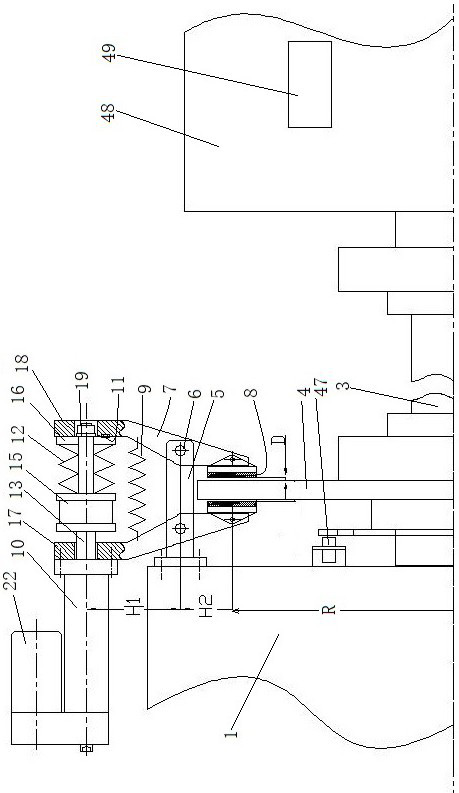
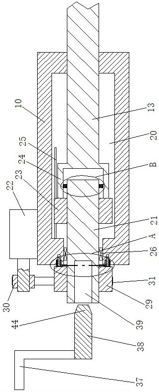
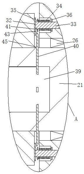
[0027] see Figure 1 to Figure 7 , a wind turbine blade rotating shaft braking system, including a gearbox 1, a rotating blade rotating shaft 3 connected to the gearbox, a brake disc 4 arranged on the fan rotating shaft, a control unit, and a brake disc for detecting the rotational speed A rotational speed sensor 47, a power sensor 49 for detecting the output power of the generator 48, and several brakes 50 distributed along the circumferential direction of the brake disc.

[0028] The brake includes a support 5 , a driving force detection unit and two scissor arms 7 whose middle parts are hinged on the support through pin shafts 6 . Two scissor arms are symmetrically distributed on both axial sides of the brake disc. One end of the scissor arm is provided with a friction plate 8 for cooperating with the brake disc, and the other end is connected together by an ele...


PUM


Abstract

The invention relates to a braking system for a fan blade rotating shaft of a wind generating set. The braking system comprises a gear box, the fan blade rotating shaft rotationally connected to the gear box, a brake disc arranged on the fan blade rotating shaft, a support and two scissor arms with the middles hinged to the support through pin shafts, the two scissor arms are distributed on the two axial sides of the brake disc, one end of each scissor arm is provided with a friction plate used for being matched with the brake disc, the other end of each scissor arm enables the corresponding friction plate to be connected to an electric push rod of the brake disc in a butt-joint mode by driving the scissor arm to rotate with the corresponding pin shaft as the axis, and the support is fixedly connected with the gear box. The first purpose of the invention is to provide a wind generating set fan blade rotating shaft brake which does not generate oil leakage information, and the problem of oil leakage caused by an oil pressure type brake in the prior art is solved.

Description

technical field [0001] The invention relates to the technical field of wind power generators, in particular to a braking system for a rotor shaft of a wind power generator. Background technique [0002] The brake is an important part of the wind turbine, and the braking reliability of the brake directly affects the safe operation of the wind turbine. The main functions of the brake are: when the wind turbine is shut down in an emergency, the high-speed shaft brake will act to stop the wind rotor completely. At present, high-speed shaft brakes mainly use hydraulic disc brakes, hydraulic pressure brakes, pressure release is separated under the action of springs, and the hydraulic system has the disadvantage of oil leakage. In addition, the existing brake loses its braking effect after the system is shut down (the system is powered off), and the wind wheel is in a state of being able to swing, so that the safety during maintenance is poor. At the same time, the braking force ...

Claims


Application Information

Patent Timeline
Patent Type & Authority Applications(China)
IPC IPC(8): F03D7/02F03D80/00
CPCF03D7/0244F03D7/0248F03D80/00Y02E10/72
Inventor 王记彩徐意
Owner JIAXING NANYANG POLYTECHNIC INST
Why Eureka
Try Eureka