Hydraulic self-adjusting air compressor

An air compressor and self-regulating technology, which is applied in the direction of liquid variable capacity machinery, mechanical equipment, variable capacity pump components, etc., can solve the problems of small delivery pulse, large output pulse of compressed gas, self-compensation of loss and closed channels, etc. To achieve the effect of avoiding large air pressure fluctuations, improving stability and reducing gas pulse

Active Publication Date: 2021-11-30
湖北双剑鼓风机股份有限公司
View PDF5 Cites 0 Cited by
  • Summary
  • Abstract
  • Description
  • Claims
  • Application Information

AI Technical Summary

Problems solved by technology

[0005] Aiming at the deficiencies in the use of the existing hydraulic air compressors proposed in the background technology, the present invention provides a hydraulic self-regulating air compressor, which has the functions of reciprocating compressed gas pushing, compressed gas storage, and reciprocating compressed gas delivery. The pulse is small, the storage compressed gas pressure reaches the standard before it enters the reciprocating transportation, the compressed gas self-locks to maintain the gas pressure in the gas storage chamber when the power is off, and the advantages of closing the channel for the air pressure loss in the gas storage chamber are self-compensation, which solves the problem of compression in the above-mentioned background technology. The technical problem of large and unstable gas output pulse

Method used


Image

  • Hydraulic self-adjusting air compressor
  • Hydraulic self-adjusting air compressor
  • Hydraulic self-adjusting air compressor

Examples


Embodiment Construction

[0027] The following will clearly and completely describe the technical solutions in the embodiments of the present invention with reference to the accompanying drawings in the embodiments of the present invention. Obviously, the described embodiments are only some, not all, embodiments of the present invention. Based on the embodiments of the present invention, all other embodiments obtained by persons of ordinary skill in the art without making creative efforts belong to the protection scope of the present invention.

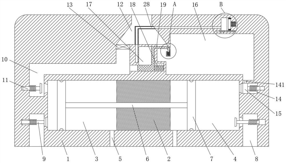
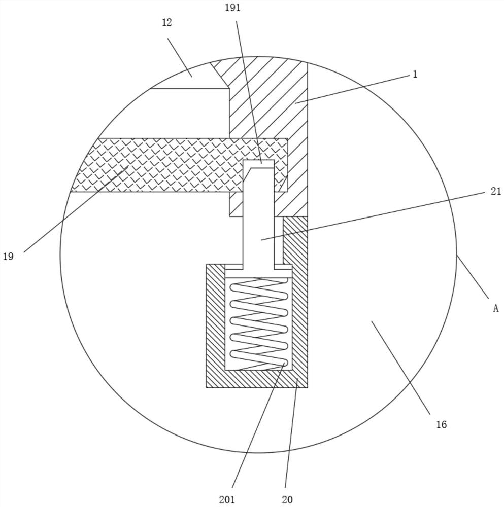
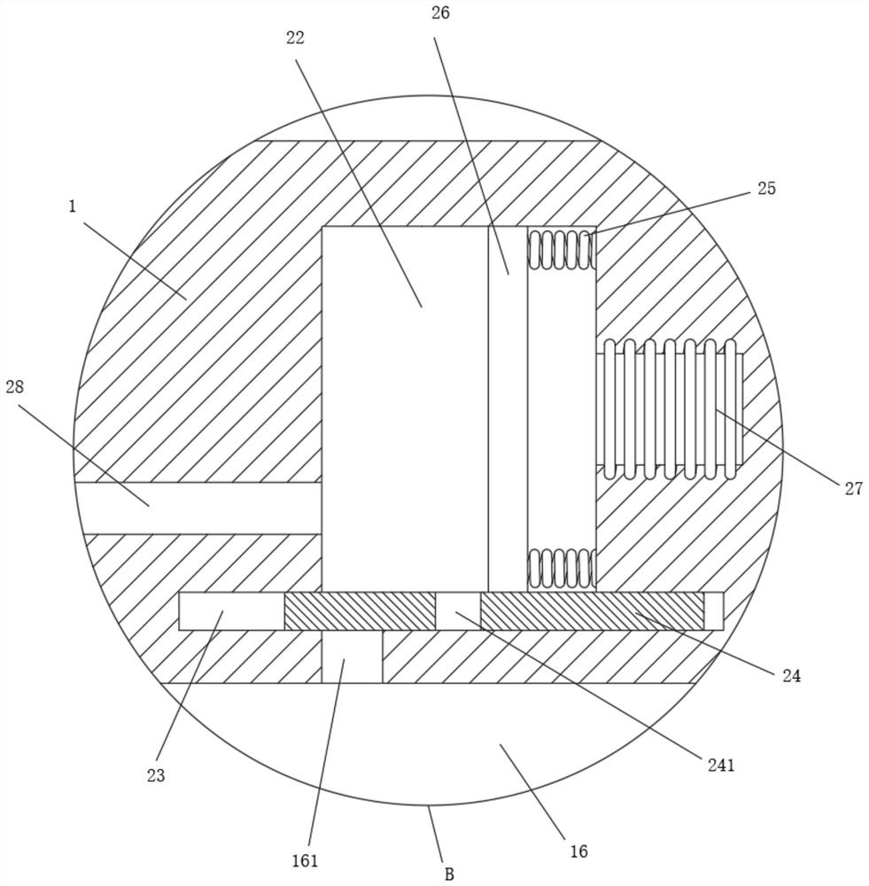
[0028] see figure 1 , Figure 4 , Figure 6-Figure 7 , a hydraulic self-regulating air compressor, including a base 1, a hydraulic cylinder located in the base 1, an intake channel 8 located on one side of the hydraulic cylinder, an intake valve 9, an air outlet channel 10, an exhaust valve 11 and an exhaust Channel 12, the center of the hydraulic cylinder is fixedly connected with a positioning seat 2, and the positioning seat 2 divides the hydraulic cylind...


PUM


Abstract

The invention relates to the technical field of mechanical industries, and discloses a hydraulic self-adjusting air compressor. The hydraulic self-adjusting air compressor comprises a base, a hydraulic cylinder located in the base, an air inlet channel located in one side of the hydraulic cylinder, an air inlet valve, an air outlet channel, an exhaust valve and an exhaust channel. A positioning seat is fixedly connected to the center of the hydraulic cylinder, the positioning seat divides the hydraulic cylinder into a compression cylinder I and a compression cylinder II, a transition cavity is formed in one end of the base, and an exhaust valve I is movably connected in the transition cavity in a sleeved mode. Through a designed air storage cavity, a designed one-way valve and a designed movable plate, when compressed air is output from the one-way valve, an opening of the air storage cavity can be closed by extruding the movable plate, unnecessary loss of the compressed air in the air storage cavity is avoided, and when the compression cylinder I conducts an air suction action, the movable plate can rebound to open the air storage cavity when pressure is lost; and the air compressor can continuously output the compressed gas, the air pulse output by the air compressor is reduced, and the output stability of the compressed gas is improved.

Description

technical field [0001] The invention relates to the technical field of machinery industry, in particular to a hydraulic self-regulating air compressor. Background technique [0002] An air compressor is a device that compresses gas. Its working principle is that the piston in the compression cylinder opens the intake valve to inhale air under the operation of the crank linkage mechanism or hydraulic control system, and then pushes the piston to compress the air and discharge it from the exhaust valve. high pressure air. [0003] The existing hydraulically driven air compressor usually realizes the reciprocating motion of the piston by means of a reversing valve, that is, with the cooperation of the electromagnetic reversing valve and the displacement sensor, and through the control of the circuit board, the purpose of the reversing movement of the piston is achieved. This method is used , It can make the air compressor shorten the discharge time of compressed gas, reduce th...

Claims


Application Information

Patent Timeline
Patent Type & Authority Applications(China)
IPC IPC(8): F04B35/02F04B39/08F04B49/00F04B49/24
CPCF04B35/008F04B39/08F04B49/002F04B49/24
Inventor 付相银
Owner 湖北双剑鼓风机股份有限公司
Why Eureka
Try Eureka