Wide-temperature nanoparticle counter

A nanoparticle and counter technology, applied in individual particle analysis, particle and sedimentation analysis, instruments, etc., can solve the problems that cannot meet the needs of wide temperature nanoparticle measurement, and achieve the effect of accurate counting

Active Publication Date: 2021-11-30
BEIHANG UNIV
View PDF9 Cites 2 Cited by
  • Summary
  • Abstract
  • Description
  • Claims
  • Application Information

AI Technical Summary

Problems solved by technology

There are many sources of air pollutants, and their temperature is also distributed from room temperature to high temperature. The existing particle metering device cannot meet the current measurement requirements for the number of wide-temperature nanoparticles.

Method used


Image

  • Wide-temperature nanoparticle counter
  • Wide-temperature nanoparticle counter
  • Wide-temperature nanoparticle counter

Examples


Embodiment 1

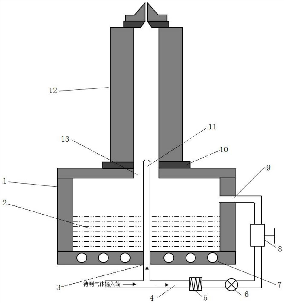
[0044] see figure 1 , the present embodiment provides a kind of wide-temperature nanoparticle counter, this wide-temperature nanoparticle counter comprises: intake shunt structure, saturator, condenser 12 and optical counter, saturator is connected with condenser 12, and condenser 12 is connected with The optical counters are connected, and the saturator, the condenser 12 and the optical counter are all provided with a temperature control unit for adjusting and controlling the temperature of the saturator, the condenser 12 and the optical counter. The temperature of the saturator is higher than the temperature of the condenser, and the liquid working medium whose thermal diffusivity is greater than the mass diffusivity is stored in the saturator. The gas to be tested is divided into two paths after it enters the input port of the gas to be tested. One path enters the pretreatment pipeline 4 for filtration and then enters the saturator, and carries the working medium vapor in t...

Embodiment 2

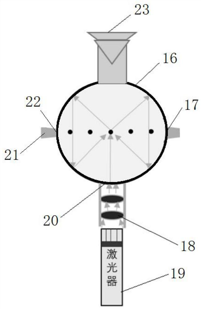
[0066] Such as image 3 As shown, the optical particle counter includes: a scattered light collection device, an aerosol particle collimation structure and a laser. Among them, see image 3 , in this embodiment, the scattered light collecting device is preferably an integrating sphere 16 . The integrating sphere 16 is provided with an aerosol particle inlet 22 , an aerosol particle outlet 17 and a laser irradiation inlet 20 . The aerosol particle collimating structure is used to linearly transport all the aerosol particles entering the integrating sphere 16 from the aerosol particle inlet 22 to the aerosol particle outlet 17 and discharge them from the aerosol particle outlet 17 . In order to avoid the phenomenon that many aerosol particles remain in the integrating sphere 16 and cannot be discharged. The laser light emitted by the laser 19 enters the integrating sphere 16 through the laser irradiation entrance 20, and the laser path intersects the movement path of the aero...

Embodiment 3

[0087] Such as Figure 14 As shown, the aerosol particle dilution system includes: a primary dilution pipeline 33 and a secondary dilution pipeline 34 . Wherein, the primary dilution pipeline 33 includes a first input pipeline 331, a second input pipeline 334 and a first gas mixing module 335, the first input pipeline 331 is connected to the gas to be detected, and the second input pipeline 334 is connected to the pure gas . Both the output end of the first input pipeline 331 and the output end of the second input pipeline 334 communicate with the input end of the first gas mixing module 335 . The secondary dilution pipeline 34 includes a first branch 341, a second branch 342 and a second gas mixing module 345, the first branch 341 is equipped with a purification filter module 343, the output end of the first branch 341 and the second The output end of the branch circuit 342 is connected to the output end of the particulate matter dilution system after converging at the seco...


PUM

PropertyMeasurementUnit
thermal conductivityaaaaaaaaaa

Abstract

The invention discloses a wide-temperature nanoparticle counter. The wide-temperature nanoparticle counter comprises an air inlet shunting structure, a saturator, a condenser and an optical counter, wherein the saturator, the condenser and the optical counter are communicated in sequence, the saturator, the condenser and the optical counter are all provided with temperature control units, and a liquid working medium of which the thermal diffusion coefficient is greater than the mass diffusion coefficient is stored in the saturator. According to the invention, to-be-detected gas is divided into two paths through the air inlet shunting structure, one path is filtered, enters the saturator and carries working medium steam to enter the condenser, and the other path enters the condenser from the center of the bottom of the condenser through a capillary tube or a micropore channel and is mixed with the gas carrying the working medium steam, wherein the working medium is selected from alcohols, silicone oil, esters or a solution formed by mixing at least two of the silicone oil, the esters and the alcohols; and aiming at different to-be-detected sample gas temperatures, different liquid working media are selected, so that effective measurement of the number concentration of the nanoparticles in a wide temperature range is realized.

Description

technical field [0001] The invention relates to the field of particle counting, in particular to a wide temperature nanometer particle counter. Background technique [0002] At present, the frequent occurrence of smog weather has aroused the public's close attention to atmospheric particulate pollutants. A large number of studies have shown that the smaller the particle size, the easier it is to penetrate into the human body. Nano-scale particles can directly reach the alveoli, and even enter the brain with the blood circulation, causing irreversible damage to the human body and causing great harm. In addition, motor vehicle and aircraft engine emission regulations also limit the number concentration of nanoparticles in exhaust gas. The measurement of fine particles is therefore fundamental for the study of air pollution and compliance with the latest emission regulations. There are many sources of air pollutants, and their temperature is also distributed from room tempera...

Claims


Application Information

Patent Timeline
Patent Type & Authority Applications(China)
IPC IPC(8): G01N15/14
CPCG01N15/1425G01N2015/1486
Inventor 陈龙飞马啸沈祺峰孙琪文张帅虎
Owner BEIHANG UNIV
Why Eureka
Try Eureka