
Wafer exposure method

An exposure method and wafer technology, which are applied in microlithography exposure equipment, photolithography process exposure devices, optics, etc., can solve the problems of reduced lithography accuracy, impact on wafer alignment, and low alignment mark recognition accuracy, etc. Achieve the effect of improving lithography accuracy and precise positioning

Pending Publication Date: 2021-11-30
安徽光智科技有限公司
View PDF0 Cites 0 Cited by
  • Summary
  • Abstract
  • Description
  • Claims
  • Application Information

AI Technical Summary

Problems solved by technology

[0005] The purpose of the present invention is to at least solve one of the above-mentioned technical defects, especially in the prior art when the wafer is exposed after gluing, due to the interference and refraction of light, the recognition accuracy of the alignment mark on the wafer Low, which affects the alignment of the wafer, resulting in a technical defect that reduces the accuracy of lithography

Method used

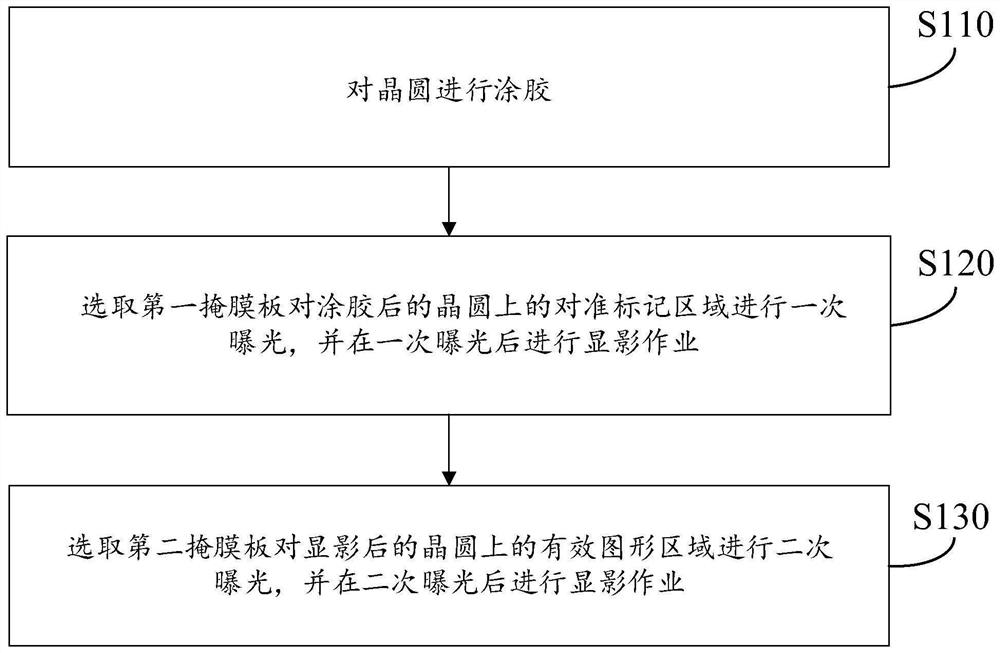
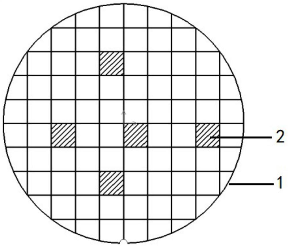

Image

  • Wafer exposure method
  • Wafer exposure method
  • Wafer exposure method

Examples


Embodiment Construction

[0026] The following will clearly and completely describe the technical solutions in the embodiments of the present invention with reference to the accompanying drawings in the embodiments of the present invention. Obviously, the described embodiments are only some, not all, embodiments of the present invention. Based on the embodiments of the present invention, all other embodiments obtained by persons of ordinary skill in the art without making creative efforts belong to the protection scope of the present invention.

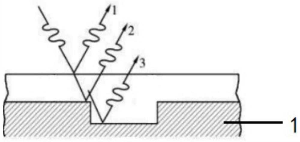
[0027] In the prior art, when using a photolithography machine for exposure, it is necessary to collect alignment marks on the wafer 1 to align the position of the wafer 1 . However, currently when collecting the alignment marks on wafer 1, such as figure 1 as shown, figure 1 When the wafer 1 is exposed after glue coating, the recognition accuracy of the alignment marks on the wafer 1 is low due to the interference refraction of light, which affects the align...


PUM


Abstract

The invention provides a wafer exposure method. When the wafer is exposed, firstly, the alignment mark area on the glued wafer is exposed through the first mask plate, and the development operation is carried out on the alignment mark area, so that when the secondary exposure is carried out, the alignment mark in the alignment mark area on the wafer can be clearly exposed, and exposure operation is carried out at the moment, so that the wafer can be accurately positioned, and the photoetching precision is effectively improved.

Description

technical field [0001] The invention relates to the technical field of semiconductor photolithography, in particular to a wafer exposure method. Background technique [0002] With the development of semiconductor technology, the density of integrated circuits is getting higher and higher, and the feature size is getting smaller and smaller. Among them, in the semiconductor process, photolithography and exposure processes play a pivotal role. In the manufacturing process of semiconductor devices, the patterning of various layers of thin films and ion implantation of semiconductors are defined by photolithography. The specific steps include: spin-coating photoresist on the surface of the wafer to form a layer of photolithography The photoresist layer is exposed and developed to transfer the pattern on the mask plate to the photoresist layer on the wafer surface. [0003] In the prior art, when a photolithography machine is used for exposure, alignment marks on the wafer need...

Claims


Application Information

Patent Timeline
Patent Type & Authority Applications(China)
IPC IPC(8): G03F9/00G03F7/20
CPCG03F9/7003G03F7/2024
Inventor 赵雪城杨晓杰李海涛黄添萍赵龙
Owner 安徽光智科技有限公司
Learn More