
Lead frame feeding and conveying device

A technology of lead frame and conveying device, which is applied in the direction of conveyors, conveyor objects, transportation and packaging, etc., which can solve the problem of inability to ensure that the lead frame can be accurately moved to the next station, poor stability and accuracy of lead frame transportation, and inconvenience Problems such as installation and commissioning of the device, to prevent deviating from the track, improve adsorption stability, and prevent slipping

Active Publication Date: 2021-11-30
四川富美达微电子有限公司
View PDF8 Cites 5 Cited by
  • Summary
  • Abstract
  • Description
  • Claims
  • Application Information

AI Technical Summary

Problems solved by technology

Because the lead frame will slip due to the way of friction, it is impossible to ensure that the lead frame moves to the next position accurately, so it is necessary to add a position detection sensor to ensure that the lead frame is in place
However, the structure of this kind of device is relatively complicated, and there are many electrical control links, which is not only inconvenient for installation and debugging of the device, but also has a relatively high failure rate in later use.
Moreover, the transportation method using friction will lead to poor stability and accuracy of lead frame transportation.

Method used


Image

  • Lead frame feeding and conveying device
  • Lead frame feeding and conveying device
  • Lead frame feeding and conveying device

Examples


Embodiment Construction

[0042] In order to make the purpose, technical solutions and advantages of the embodiments of the present invention clearer, the embodiments of the present invention will be described in detail below in conjunction with the accompanying drawings, but the embodiments described in the present invention are some of the embodiments of the present invention, not all of them .

[0043] It should be noted that like numerals and letters denote similar items in the following figures, therefore, once an item is defined in one figure, it does not require further definition and explanation in subsequent figures.

[0044] In describing the present invention, it should be noted that the terms "centre", "upper", "lower", "left", "right", "vertical", "horizontal", "inner", "outer" etc. indicate The orientation or positional relationship of the invention is based on the orientation or positional relationship shown in the drawings, or the orientation or positional relationship that is usually p...


PUM


Abstract

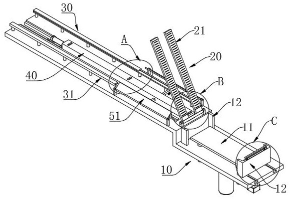
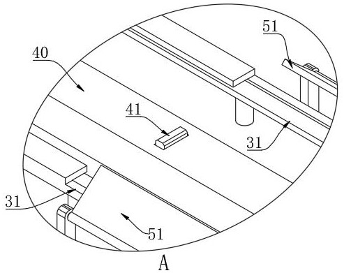
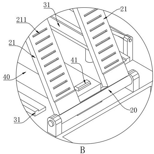
The invention provides a lead frame feeding and conveying device, which comprises a material storage mechanism, an overturning suction disc and a conveying mechanism, wherein the material storage mechanism is provided with a lifting plate which moves in the vertical direction and is used for storing a lead frame, the overturning suction disc is rotationally arranged, the front section of the overturning suction disc is a pair of suction plates which are arranged in parallel at intervals, a plurality of vent holes are formed in one face of each suction plate, the conveying mechanism comprises a pair of rails arranged at intervals, the rails are of an L-shaped structure, a pushing plate is movably arranged in the middle of the rails in the length direction, a plurality of shifting sheets are arranged on the top face of the pushing plate at intervals in the length direction, the interval size is larger than the length of the lead frame, the shifting sheet can protrude out of or be hidden in the pushing plate, gaps are formed between the pushing plate and the rails on the two sides, and when the overturning suction disc is turned to the conveying mechanism, the two suction plates are located in the gaps between the pushing plate and the rails on the two sides correspondingly. According to the invention, high adsorption firmness is achieved, the lead frame can be prevented from falling off in the feeding process, and the lead frame can be conveyed more stably and accurately.

Description

technical field [0001] The invention belongs to the technical field of semiconductor device packaging, in particular to a lead frame feeding and conveying device. Background technique [0002] For semiconductor devices, chips are usually solidified on the leads of the lead frame, and then individual devices are formed through processes such as packaging and rib cutting. The leads of the lead frame usually have a bent structure, so that a part of the lead protrudes from the entire plane of the lead frame. In the production process, multiple processes require fast feeder delivery of the lead frame. When feeding, most of the existing equipment adopts a plurality of straws to absorb the lead frame through negative pressure; and usually when feeding the machine, the protruding side of the pin is set on the top to facilitate sticking the core; however In this case, there are relatively few positions on the lead frame for suction of the straw, and the overall area will not be too...

Claims


Application Information

Patent Timeline
Patent Type & Authority Applications(China)
IPC IPC(8): H01L21/677B65G47/91B65G19/02
Inventor 曾尚文刘高宸陈久元杨利明
Owner 四川富美达微电子有限公司
Learn More