Combined antenna for millimeter wave automobile radar

A technology of automotive radar and combined antenna, which is applied to antennas, antennas, resonant antennas and other directions suitable for movable objects, can solve the problems of increasing the cost of the radar system, the area occupied by the antenna is not effectively used, and the grating lobe, etc., to achieve The structure is simple, the design is easy, and the effect of utilizing the antenna area

Pending Publication Date: 2021-11-30
WENZHOU ADVANCED MFG TECH INST OF HUAZHONG UNIV OF SCI & TECH
View PDF0 Cites 0 Cited by
  • Summary
  • Abstract
  • Description
  • Claims
  • Application Information

AI Technical Summary

Problems solved by technology

However, on the one hand, the distance between the radiating sides of traditional grid antennas is about one times the wavelength of the medium, which leads to the problem of grating lobes due to excessive array element spacing when designing phased arrays and MIMO arrays with grid antennas.
On the other hand, the "hollow" structural characteristics of the grid antenna lead to the ineffective use of the area occupied by the antenna, which virtually increases the cost of the radar system

Method used


Image

  • Combined antenna for millimeter wave automobile radar
  • Combined antenna for millimeter wave automobile radar
  • Combined antenna for millimeter wave automobile radar

Examples


Embodiment Construction

[0021] The patent of the present invention will be further described in detail below in conjunction with the embodiments and accompanying drawings, but the scope of protection claimed by the patent of the present invention is not limited to the scope involved in the embodiments.

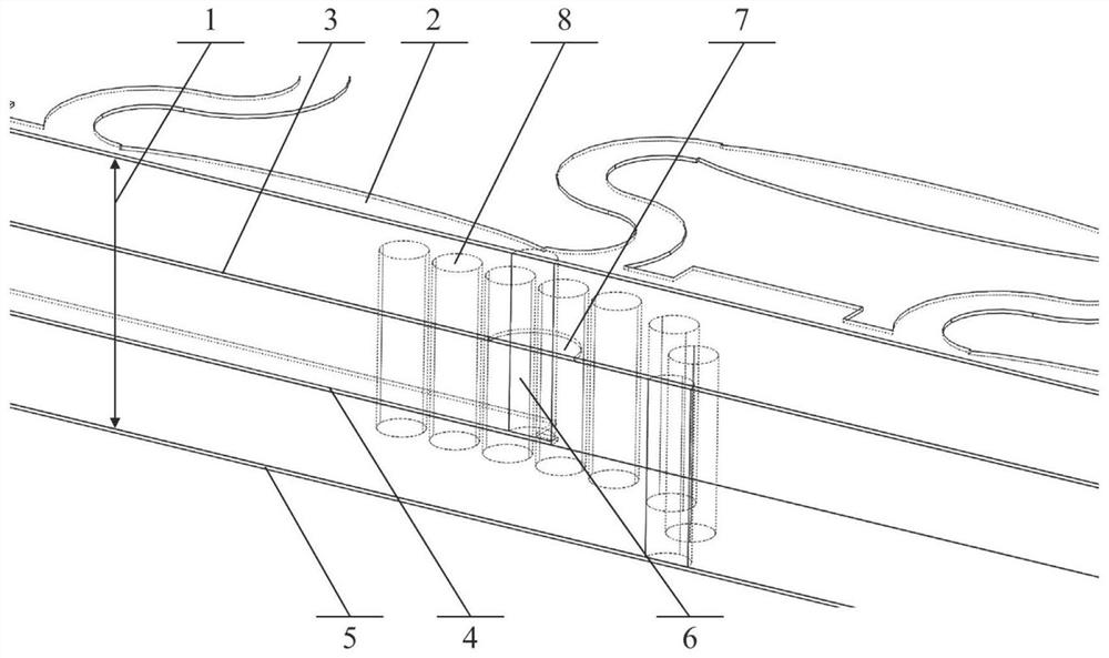
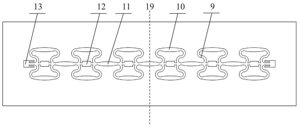
[0022] The antenna structure provided by the patent of the present invention consists of figure 1 As mentioned above, the overall structure includes three layers of dielectric material and four layers of metal. The metal layers include the radiation layer, the antenna reflector layer, the stripline feed layer and the bottom floor layer. A top view of the radiative layer by figure 2 As mentioned above, more than two grid radiating units are etched to meet the requirements of differential feeding. The size of each grid unit is exactly the same, and the length and width of the connecting section between the units are also consistent with the radiation side. The advantage of this is to reduce the diffi...


PUM


Abstract

The invention discloses a combined antenna for a millimeter wave automobile radar. The combined antenna is composed of three layers of dielectric materials and four layers of metal. The metal layer comprises a radiation layer, an antenna reflection layer, a strip line feed layer and a bottom floor layer. The radiation layer is etched with more than two identical grid radiation units which are arranged at equal intervals, and non-radiation edges of the grid units are bent arcs instead of traditional straight lines. The radiation edge replaces a traditional same-width microstrip line with a gradually-changed microstrip line, and the length and width of the connecting section between the units are consistent with those of the radiation edge of the grid unit, so that the design difficulty of the antenna is reduced. The patch units are added in the blank areas in the middle of the grid units and are connected with the non-radiation edges of the grids through the microstrip lines, and the patch units and the connecting sections between the units form a series patch antenna, so that the area of the antenna is effectively utilized. Because the area in the middle of the grid unit is small, the frequency of the resonant mode generated by the patch antenna is slightly higher than that of the grid antenna, the radiation units in two forms form a combined antenna effect, and the working bandwidth of the antenna is widened by the radiation of the generated two groups of resonant modes. The antenna adopts a via hole for feeding, feeding points are bilaterally symmetrical about the center of the linear array, and the via hole penetrates through a through hole in the antenna reflection ground layer and is connected with the strip line feeding layer; the strip line feed layer comprises a T-shaped power divider and a phase shifter realized by using an additional length, and is used for realizing differential feed. The antenna is simple in structure, easy to design, low in cost and suitable for millimeter wave band automobile radars.

Description

technical field [0001] The patent of the present invention relates to wireless communication equipment, in particular to a vehicle-mounted radar antenna, specifically a combined antenna for millimeter-wave vehicle radar designed by planar technology. Background technique [0002] With the development of the automobile industry, whether it is the detection and early warning of the current automobile anti-collision system or the application of driverless car technology in the future, automobile radar is receiving more and more attention. Compared with ultrasonic, infrared, and laser system radars, millimeter wave automotive radar has the characteristics of large bandwidth, high resolution, small size, low cost, and can work in any harsh weather environment. The serial microstrip patch antenna has low profile, compact structure and easy integration, and is currently the most widely used antenna form in millimeter wave automotive radar. In recent years, with the rapid developme...

Claims


Application Information

Patent Timeline
Patent Type & Authority Applications(China)
IPC IPC(8): H01Q1/36H01Q1/50H01Q1/48H01Q15/14H01Q9/04H01Q13/08H01Q1/32
CPCH01Q1/36H01Q1/50H01Q1/48H01Q15/14H01Q9/0407H01Q13/08H01Q1/3233
Inventor 王晓川严正罡吕文中雷文梁飞汪小红范桂芬付明
Owner WENZHOU ADVANCED MFG TECH INST OF HUAZHONG UNIV OF SCI & TECH
Why Eureka
Try Eureka