Multi-view-field array antenna for millimeter wave automobile radar

A technology for automotive radar and array antennas, which is applied to antennas, antennas, resonant antennas and other directions suitable for movable objects, which can solve the problems of increasing the difficulty of front-end signal processing, redundancy of transceiver link resources, and avoiding grating lobes. problems, wide beam widths, the need to reduce the number of links and the effects of

Pending Publication Date: 2021-11-30
WENZHOU ADVANCED MFG TECH INST OF HUAZHONG UNIV OF SCI & TECH
View PDF0 Cites 1 Cited by
  • Summary
  • Abstract
  • Description
  • Claims
  • Application Information

AI Technical Summary

Problems solved by technology

Multiple transmit arrays activate the working status by time-sharing through the front-end RF chips. On the one hand, there is a demand for the number of chip links, resulting in redundancy of transceiver link resources.
On the other hand, it also increases the difficulty of front-end signal processing

Method used


Image

  • Multi-view-field array antenna for millimeter wave automobile radar
  • Multi-view-field array antenna for millimeter wave automobile radar
  • Multi-view-field array antenna for millimeter wave automobile radar

Examples


Embodiment Construction

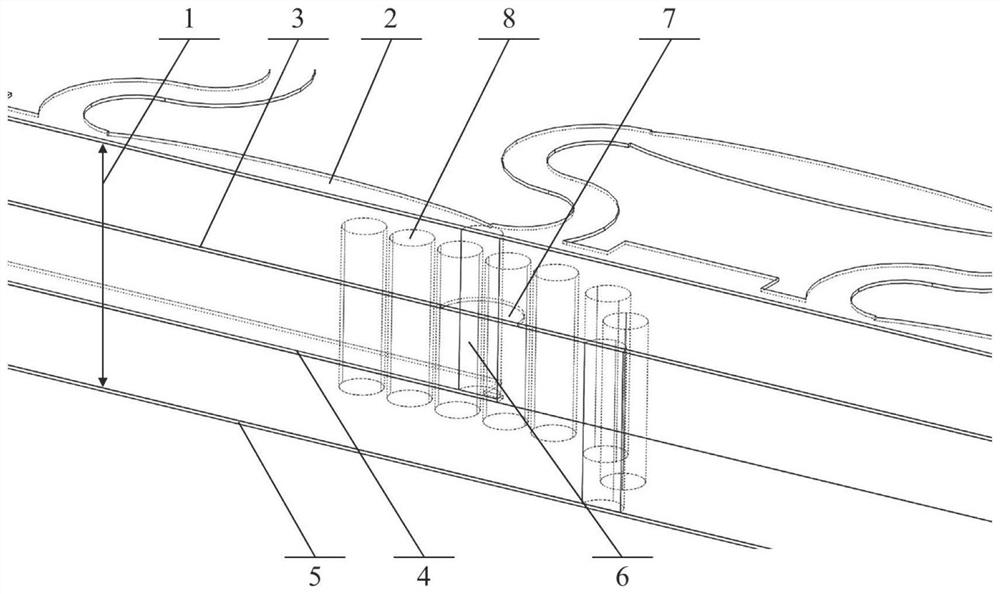
[0022] The patent of the present invention will be further described in detail below in conjunction with the embodiments and accompanying drawings, but the scope of protection claimed by the patent of the present invention is not limited to the scope involved in the embodiments.

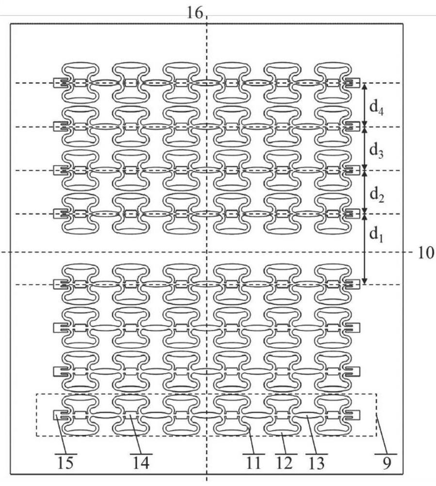
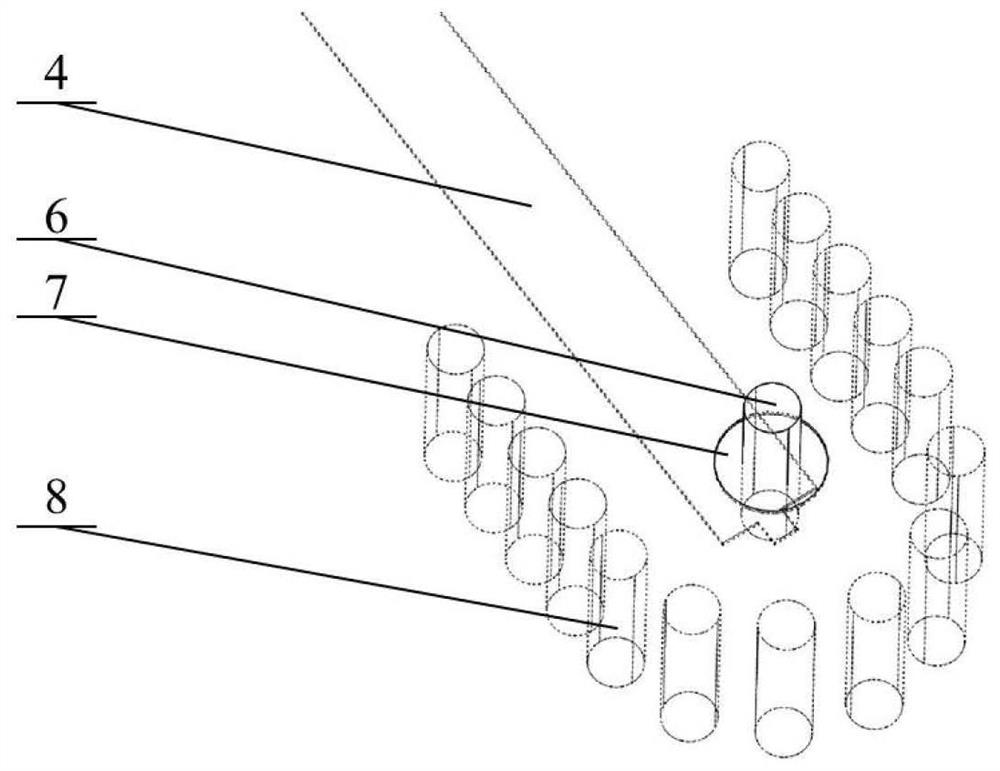
[0023] The antenna structure provided by the patent of the present invention consists of figure 1 As mentioned above, the overall structure includes three layers of dielectric material and four layers of metal. The metal layers include the radiating layer, the antenna reflector layer, the stripline feed layer and the bottom floor layer. A top view of the radiative layer by figure 2 As mentioned above, an array composed of four or more combined antennas is etched with an array spacing d 1 、d 2 、d 3 、d 4 and feed amplitude and feed phase are symmetrical about the center line of the array. According to the number of array elements and the number of required multi-fields, through the array beamform...


PUM


Abstract

The invention discloses a multi-view-field array antenna for a millimeter wave automobile radar, which is composed of three layers of dielectric materials and four layers of metals. The metal layers comprise a radiation layer, an antenna reflection layer, a strip line feed layer and a bottom floor layer. An array formed by four or more combined antennas is etched on the radiation layer, and the antennas are formed by radiation units in two forms of grid units and patch units. The antennas are symmetrical about the center line of the array, each antenna is composed of more than two identical grid radiation units which are arranged at equal intervals, the non-radiation edge of each grid unit is a bent arc instead of a traditional straight line, and the radiation edge of each grid unit is a gradient microstrip line instead of a traditional microstrip line with the same width. The patch units are added in the blank areas among the grid units, and the patch units and the inter-unit connecting sections form a series patch antenna, so that the area of the antenna is effectively utilized. The beam forming design is carried out on the array, so that a directional diagram has a plurality of square shoulder-shaped features, and different view fields divided by square shoulders meet the detection requirements of the radar on targets in different distance ranges. The structure is simple, integration of multiple detection distance functions of the radar can be realized only through one emission link, the processing difficulty of front-end signals is reduced, and the antenna is suitable for millimeter wave band automobile radars.

Description

technical field [0001] The patent of the present invention relates to wireless communication equipment, in particular to a vehicle-mounted radar antenna, specifically a multi-field array antenna for millimeter-wave vehicle radar designed by planar technology. Background technique [0002] With the development of smart cars and driverless technology, automotive radar is increasingly becoming an indispensable part of the car. Compared with ultrasonic, infrared, and laser system radars, millimeter wave automotive radar has the characteristics of large bandwidth, high resolution, small size, low cost, and can work in any harsh weather environment. At present, in the millimeter-wave automotive radar, in order to realize the detection and early warning of targets in different ranges, more than one transmitting array antenna is generally required. For example, in order to detect long-distance large targets, the array size needs to be large enough to achieve high-gain narrow beams;...

Claims


Application Information

Patent Timeline
Patent Type & Authority Applications(China)
IPC IPC(8): H01Q1/36H01Q1/50H01Q1/48H01Q13/08H01Q9/04H01Q1/32H01Q21/00
CPCH01Q1/36H01Q1/50H01Q1/48H01Q13/08H01Q9/0407H01Q1/3233H01Q21/00
Inventor 王晓川严正罡吕文中雷文梁飞汪小红范桂芬付明
Owner WENZHOU ADVANCED MFG TECH INST OF HUAZHONG UNIV OF SCI & TECH
Why Eureka
Try Eureka