
A low-cost modular flat-panel electronically scanned antenna

A modular and low-cost technology, which is applied to antenna arrays, antennas, and antenna arrays that are powered independently, can solve the problems of refugee use, limited circuit layout space, and high antenna costs, to suppress grating lobes and improve anti-interference characteristics , The effect of reducing processing costs

Active Publication Date: 2021-11-12
UNIV OF ELECTRONICS SCI & TECH OF CHINA
View PDF10 Cites 0 Cited by
  • Summary
  • Abstract
  • Description
  • Claims
  • Application Information

AI Technical Summary

Problems solved by technology

However, the biggest challenge faced by the traditional phased array antenna technology and application is that the cost of the antenna is too high, and it is difficult to widely promote it to the civilian field.
With the large occupation of low-frequency spectrum resources, the research direction has been shifted to higher frequency bands. However, since the control of each antenna unit requires a corresponding transceiver circuit, the circuit layout space is very limited.

Method used


Image

  • A low-cost modular flat-panel electronically scanned antenna
  • A low-cost modular flat-panel electronically scanned antenna
  • A low-cost modular flat-panel electronically scanned antenna

Examples


Embodiment Construction

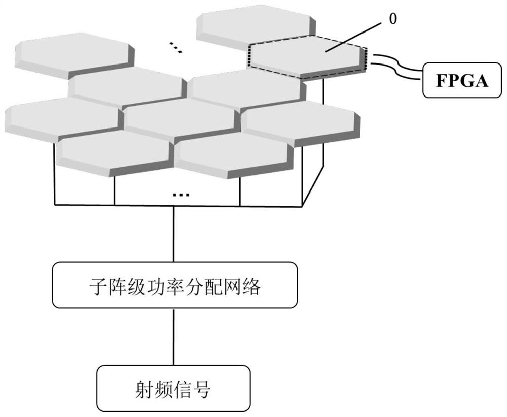
[0024] like figure 1 Shown is a low-cost modular electronically scanned array antenna system. Its structure includes a radio frequency signal module, a sub-array-level power distribution network, and multiple modular hexagonal sub-array modules (0). The sub-array splicing method can realize large-scale array design; the RF signal generated by the RF signal module is input to the power division network of the sub-array level to generate multiple RF signals of equal amplitude and phase, under the control of the programmable logic array (FPGA) control circuit , the antenna elements can generate different phase distributions, so that the main beam of the array can be flexibly switched in space.

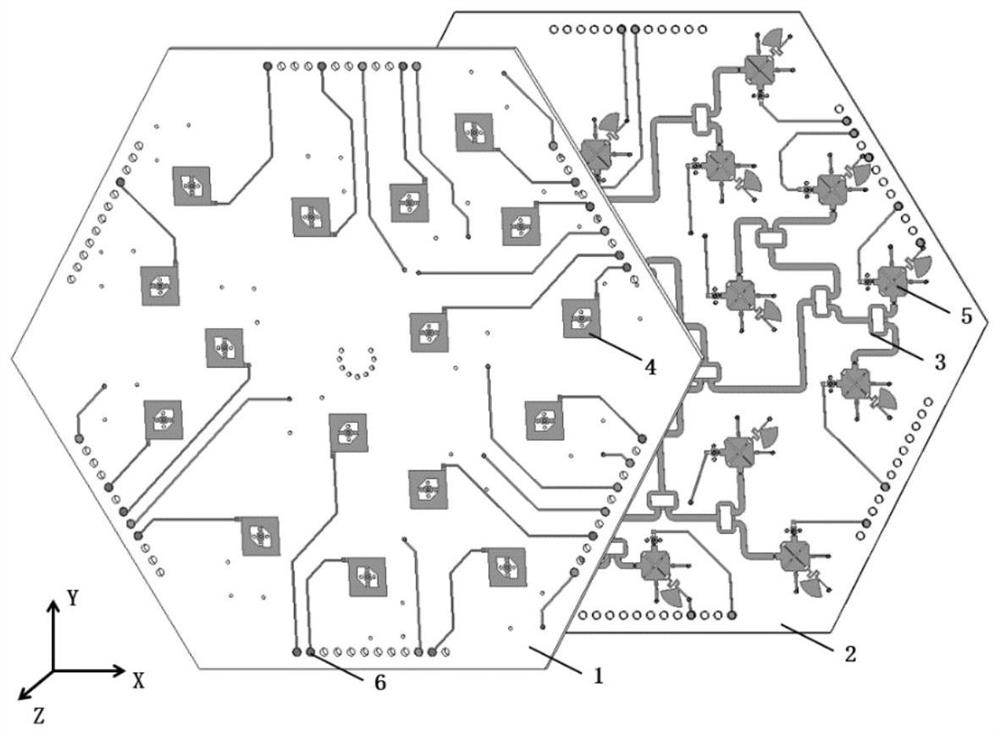
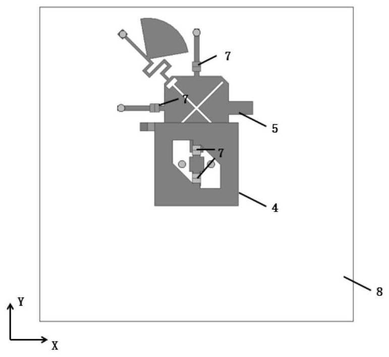
[0025] like figure 2 Shown is a schematic diagram of the modular sub-array structure. Each sub-array (0) adopts a hexagonal aperture structure, and each sub-array integrates 16 array elements (6), a 1-to-16 power division network (3) and a DC bias circuit (6). The structure of the sub...


PUM


Abstract

The invention proposes a phased array design scheme, and especially proposes an effective method for low-cost and modularization of flat-panel phased array antennas. The method of the present invention mainly includes: based on an antenna unit with an integrated phase shifting function, 16 array elements are placed on a hexagonal aperture to form a sub-array in a sparse array layout, and the modularized sub-array is spliced Large scale arrays can be realized. The beneficial effect of the present invention is that the radiation phase of each antenna unit is directly controlled to realize the two functions of "radiation" and "phase shifting" of the antenna, which can effectively suppress the grating lobes of the spliced ​​array of non-overlapping uniform sub-arrays, and simultaneously omit The external phase shifter greatly reduces the processing cost; the sub-array rotation and array element rotation are used to achieve phase compensation, which can effectively reduce the quantization sidelobe level; the sub-array synthesis technology can split a large array into multiple A small module, easy to process, assemble and maintain.

Description

technical field [0001] The invention designs a field of phased array design, and especially proposes an effective method for the low-cost modular design of flat panel phased array antennas. Background technique [0002] The phased array antenna is a type of antenna developed from an array antenna. By controlling the phase of the antenna unit through a controllable electronic phase shifter connected to the rear of the antenna, the original direction can be aligned in a certain direction within a few microseconds. The lobe shifts and projects in the other direction. Since the 1960s, phased array antennas began to show a blowout. Since then, phased array technology has been rapidly improved under the research of various countries. Phased array panel antennas have the advantages of low profile, high gain, and flexible beams. With the development of 5G applications and Internet of Things technology, the demand for phased array antennas has increased. However, the biggest challe...

Claims


Application Information

Patent Timeline
Patent Type & Authority Patents(China)
IPC IPC(8): H01Q21/06H01Q3/38
CPCH01Q3/385H01Q21/065
Inventor 杨鹏尹璐张飞聂在平
Owner UNIV OF ELECTRONICS SCI & TECH OF CHINA
Learn More