MIMO array antenna for millimeter wave automobile radar

A technology of automotive radar and array antenna, which is applied to antennas, antennas, resonant antennas and other directions suitable for movable objects, can solve the problems of low utilization of grating lobes and antenna area, affect array performance and system cost, etc., and achieve improvement Effects of aperture and degrees of freedom, radar angular resolution enhancement, and wide beamwidth

Pending Publication Date: 2021-11-30
WENZHOU ADVANCED MFG TECH INST OF HUAZHONG UNIV OF SCI & TECH
View PDF0 Cites 0 Cited by
  • Summary
  • Abstract
  • Description
  • Claims
  • Application Information

AI Technical Summary

Problems solved by technology

Due to its simple structure and high compatibility with planar manufacturing processes, grid antennas have broad application prospects in the millimeter wave band. However, due to the large spacing between radiation sides, grating lobes and antenna area are prone to occur when grid antennas are used to design arrays. Issues such as low utilization, affecting array performance and system cost

Method used


Image

  • MIMO array antenna for millimeter wave automobile radar
  • MIMO array antenna for millimeter wave automobile radar
  • MIMO array antenna for millimeter wave automobile radar

Examples


Embodiment Construction

[0021] The patent of the present invention will be further described in detail below in conjunction with the embodiments and accompanying drawings, but the scope of protection claimed by the patent of the present invention is not limited to the scope involved in the embodiments.

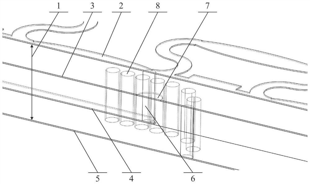
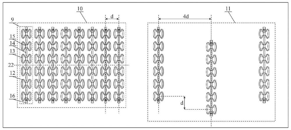
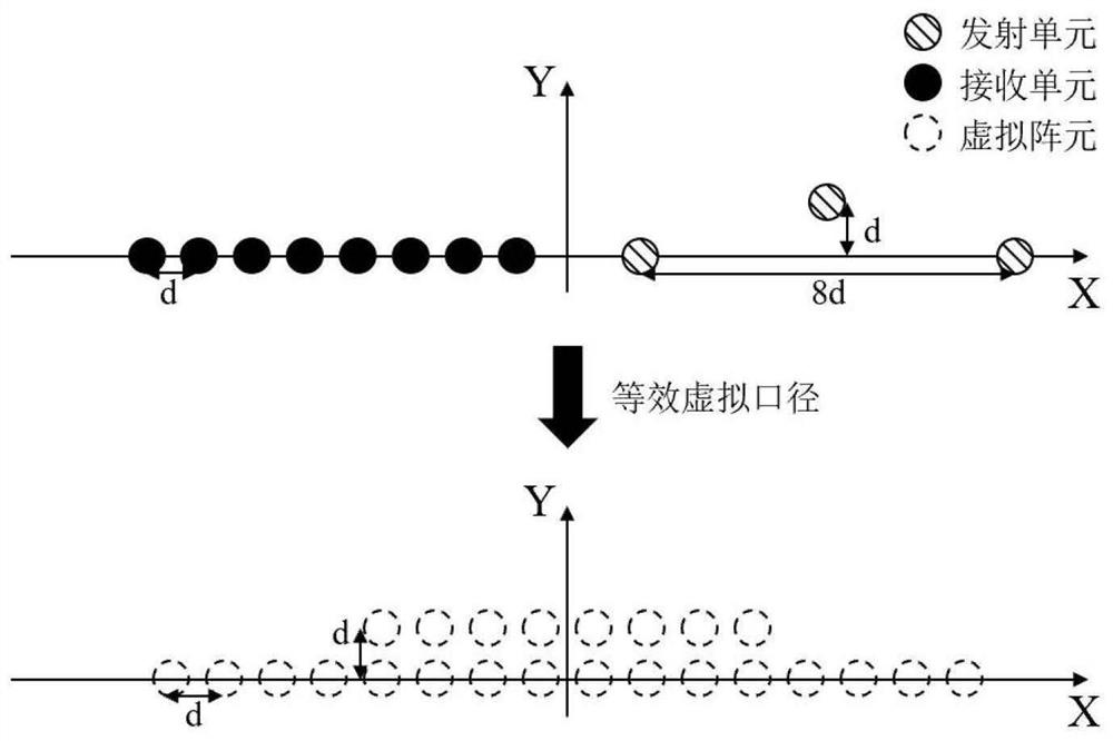
[0022] The antenna structure provided by the patent of the present invention consists of figure 1 As mentioned above, the overall structure includes three layers of dielectric material and four layers of metal. The metal layers include the radiating layer, the antenna reflector layer, the stripline feed layer and the bottom floor layer. A top view of the radiative layer by figure 2 As mentioned above, an array composed of combined antennas is etched, including a receiving array composed of the first to eighth receiving antennas uniformly arranged in the transverse direction with an array spacing of d from left to right, and a receiving array composed of uniformly arranged array spacing in the trans...


PUM


Abstract

The invention discloses an MIMO array antenna for a millimeter wave automobile radar. The MIMO array antenna is composed of three layers of dielectric materials and four layers of metal. The metal layer comprises a radiation layer, an antenna reflection layer, a strip line feed layer and a bottom floor layer. An MIMO array antenna formed by combined antennas is etched on the radiation layer, the antenna array comprises a first receiving antenna to an eighth receiving antenna which are uniformly arranged along the transverse direction at an array spacing of d and a first transmitting antenna to a third transmitting antenna which are uniformly arranged along the transverse direction at an array spacing of 4d, and the second transmitting antenna has an offset d along the longitudinal direction. The combined antenna is composed of radiation units in two forms of grid units and patch units, each antenna is composed of more than two same grid radiation units which are arranged at equal intervals, a non-radiation edge of each grid unit is formed by a bent arc instead of a traditional straight line, and a radiation edge is formed by a gradient microstrip line instead of a traditional microstrip line with the same width. The patch units are added in the blank areas among the grid units, and the patch units and the inter-unit connecting sections form a series patch antenna, so that the area of the antenna is effectively utilized. The MIMO technology is adopted to design the millimeter wave radar array antenna, and through the synthesized virtual array, on one hand, the radar pitching surface detection function is achieved, and the freedom degree of radar detection is improved; and on the other hand, the antenna aperture is widened, the radar angular resolution is improved, and the antenna is suitable for millimeter wave automobile radars.

Description

technical field [0001] The patent of the present invention relates to wireless communication equipment, in particular to a vehicle-mounted radar antenna, specifically a MIMO array antenna designed by planar technology for millimeter-wave vehicle radar. Background technique [0002] With the rapid development of unmanned driving and smart car technology in recent years, the Advanced Driver Assistance System (Advanced Driver Assistance System, ADAS) senses the surrounding environment of the car, collects environmental data, and identifies and tracks targets to assist the driver in driving safely. The purpose is to take braking measures one step faster than the driver in an emergency, greatly reducing the possibility of traffic accidents, and has become an indispensable part of the car. Millimeter-wave radar has become the main sensor of ADAS due to its long detection distance, low environmental impact, low cost, and mature technology. In order to further improve radar performa...

Claims


Application Information

Patent Timeline
IPC IPC(8): H01Q1/36H01Q1/50H01Q1/48H01Q21/00H01Q9/04H01Q1/32
CPCH01Q1/36H01Q1/50H01Q1/48H01Q21/00H01Q9/0407H01Q1/3233
Inventor 王晓川严正罡吕文中雷文梁飞汪小红范桂芬付明
Owner WENZHOU ADVANCED MFG TECH INST OF HUAZHONG UNIV OF SCI & TECH
Why Eureka
Try Eureka