
RFID tag antenna for attached on high conductive object

a high-conductive object and antenna technology, applied in the direction of resonant antennas, substantially flat resonant elements, instruments, etc., can solve the problems of low capacitance, loss of readability and/or reliability of rfid readers, and difficulty in avoiding troubles

Inactive Publication Date: 2013-05-16
NAT TAIPEI UNIV OF TECH
View PDF6 Cites 14 Cited by
  • Summary
  • Abstract
  • Description
  • Claims
  • Application Information

AI Technical Summary

Benefits of technology

The present invention provides a miniature antenna for RFID that works in the ultra-high frequency band, between 922 MHz to 928 MHz. The antenna has a ground plane that can be attached to any high conductive object. It includes a main radiation body made up of a short-circuit microstrip, a feed in microstrip, and a periphery microstrip. The antenna has a compact design and can be easily embedded in various objects. The technical effects of this invention are a miniature RFID antenna with a wide frequency range and a ground plane that can be attached to any conductive object.

Problems solved by technology

However, the readability and / or reliability by a RFID reader will be lost or be discount if a RFID chip directly disposed on an object having high conductivity such as a metal plate.
In practice, the troubles are difficult to avoid.
Furthermore, a RFID chip has features of low resistance but high capacitance and demands a miniature antenna for work normally.
All of above inferior factors will increase the difficulty of a miniature-antenna of RFID chips designation.

Method used


Image

  • RFID tag antenna for attached on high conductive object
  • RFID tag antenna for attached on high conductive object
  • RFID tag antenna for attached on high conductive object

Examples


Embodiment Construction

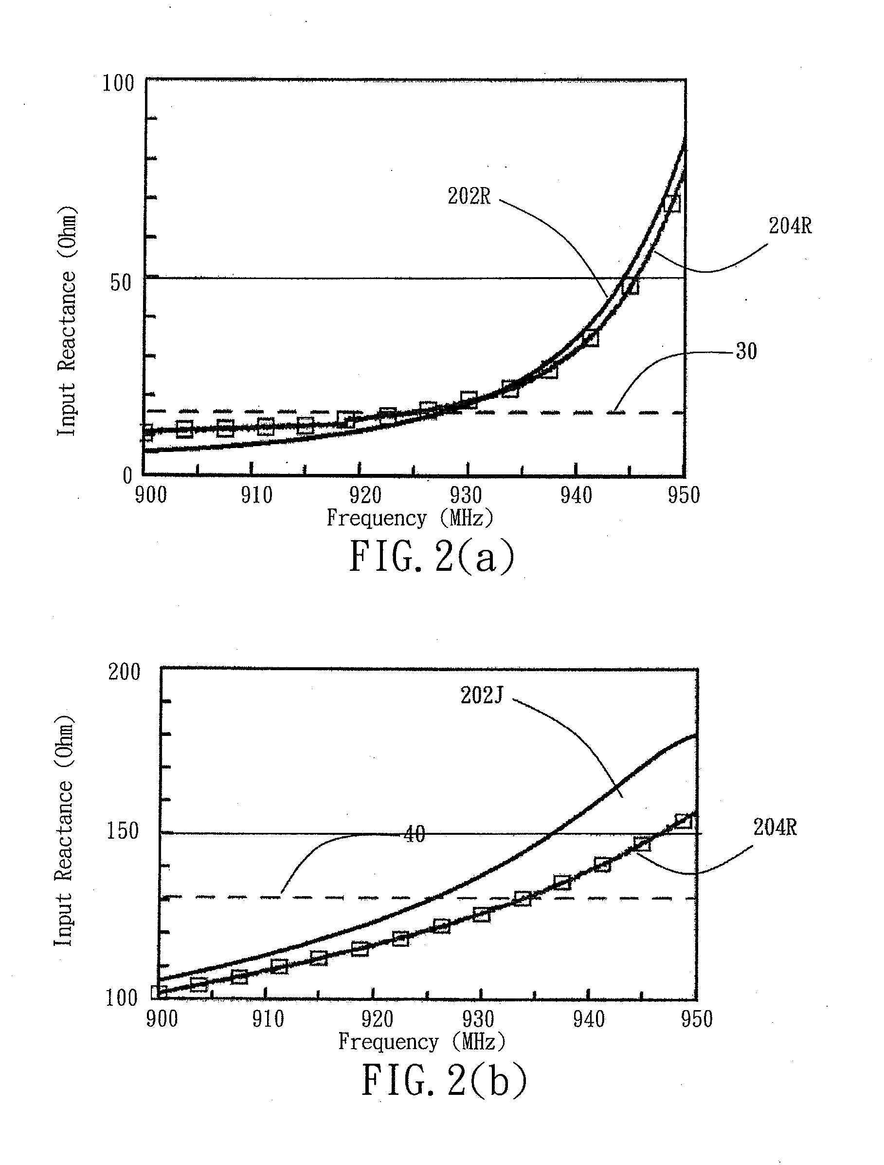
[0022]The frequency bands of RFID chips opened for public are varied with countries, typically, the frequencies including 125 KHz, 134.2 KMHz, 13.56 MHz, 850 MHz to 960 MHz in ultra-high frequency range, and 2.45 GHz-5.8 GHz in microwave range. In Taiwan, the frequency band of RFID chips opened are of 922 MHz-928 MHz. Accordingly, an equivalent circuit of a RFID chip for a working frequency of 925 MHZ, a mid value of a 922 MHZ-928 MHZ, can be expressed by a R-C (resistor-capacitors) circuit having an impendence Z=11−j131. That is a small resistance in series with a high capacitance. The following designation for a miniature antenna will base on the forgoing impedance in the frequency ban of a 922 MHZ-928 MHz. To obtain a maximum power transfer, a matched antenna for the RFID chip, the impedance would be or at least near a complex conjugate of the impendence Z.

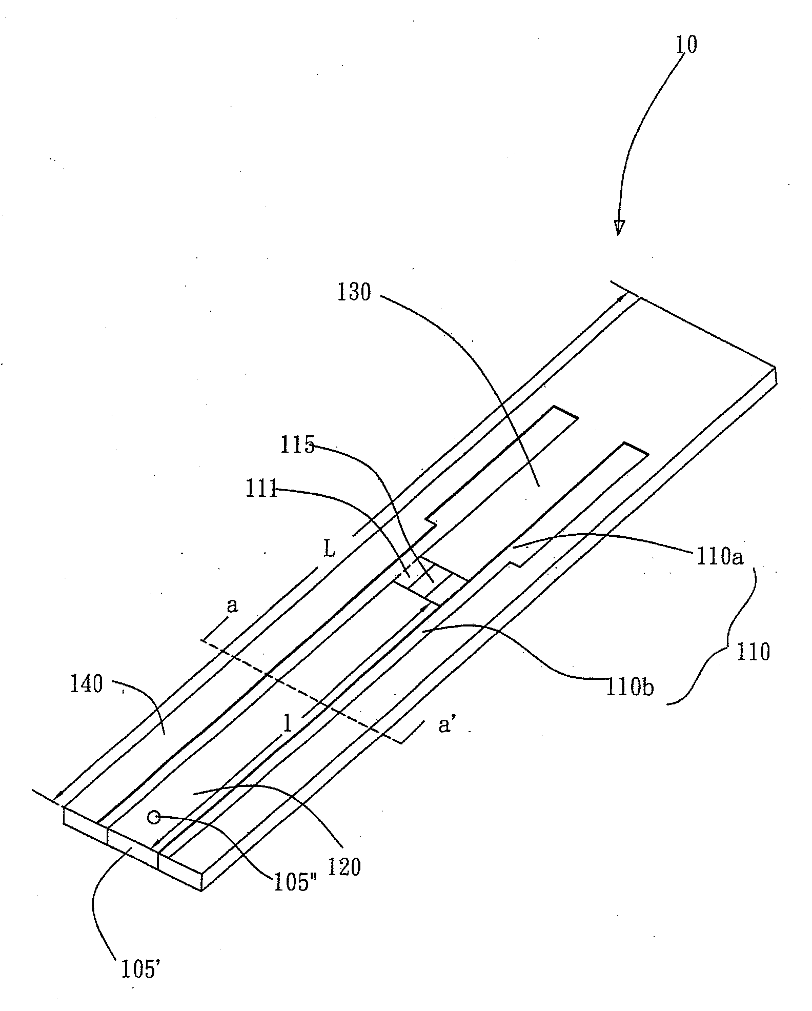
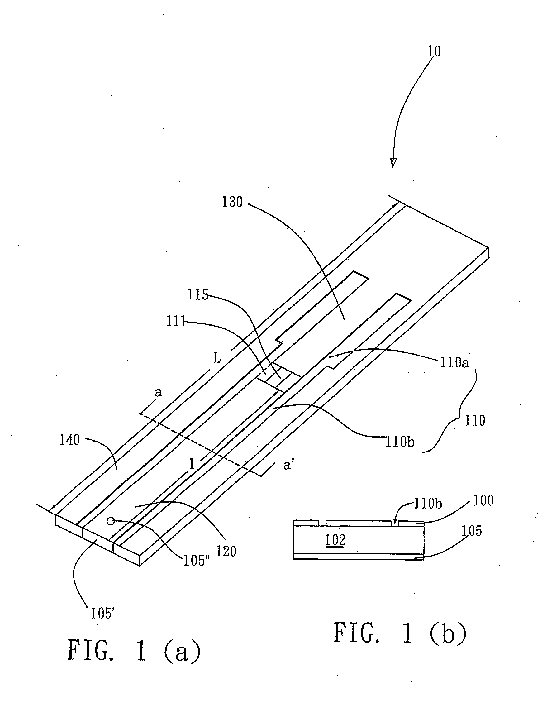
[0023]Referring to FIG. 1A, it shows a perspective diagram of a RFID antenna for ultra-high frequency according to the presen...


PUM


Abstract

An UHF RFID antenna for attached on any high conductive object is disclosed. The antenna radiation body has a first copper foil mounted thereon a backside surface of a FR4 glass fiber served as a ground plane, a second copper foil mounted thereon a front surface of the FR4 glass fiber as a main radiation plane. The main radiation plane contains two etched slits spaced each other. Each etched slit has a shape like a blade with a long handle. The two etched slits are mirror symmetry and a trench formed to connect the two etched slits for a RFID tag seated thereon so that There are short circuit microstrip and a feed-in microstrip are generated.

Description

FIELD OF THE INVENTION[0001]The present invention pertains a miniature antenna structure, particularly, to an antenna structure for an ultra-high frequency RFID chip.DESCRIPTION OF THE PRIOR ART[0002]Since the late of twentieth century, the Internet communication technology flourishes, and nowadays the communication era further leaps from a wired technology to wireless. Among the communication technologies pushing the wireless communication hit, a radio frequency identification hereinafter called RFID, may be the prominent role and cannot be lacked.[0003]RFID chip is a tiny chip, having types of an active and a passive. The active type RFID requires a battery electrically attached to provide power in any time. The passive type RFID is, however, without a battery and thus no power is consumed but it can be called back by a RFID reader. The latter provides an electromagnetic inductive current to activate the RFID. The RFID chip has a small capacity of non-volatile memory provided for ...

Claims


Application Information

Patent Timeline
Patent Type & Authority Applications(United States)
IPC IPC(8): H01Q1/38
CPCH01Q1/38H01Q1/2225H01Q9/0407G06K19/07786H01Q9/045H01Q23/00H01Q9/0442
Inventor LIN, DING-BINGWANG, CHAO-CHIEH
Owner NAT TAIPEI UNIV OF TECH
Learn More