Novel reforming furnace for preparing reducing gas

A reforming furnace and a new type of technology, applied in the metallurgy and petrochemical fields, can solve the technical and economic problems of reducing gas, and achieve the effects of saving materials, reducing floor space and improving economy.

Pending Publication Date: 2019-12-17
SINOPEC NANJING ENG & CONSTR +1
View PDF0 Cites 14 Cited by
  • Summary
  • Abstract
  • Description
  • Claims
  • Application Information

AI Technical Summary

Problems solved by technology

[0004] The purpose of the present invention is to provide a kind of equipment for producing the reducing gas of direct reduced iron in view of the

Method used


Image

  • Novel reforming furnace for preparing reducing gas
  • Novel reforming furnace for preparing reducing gas
  • Novel reforming furnace for preparing reducing gas

Examples


Embodiment 1

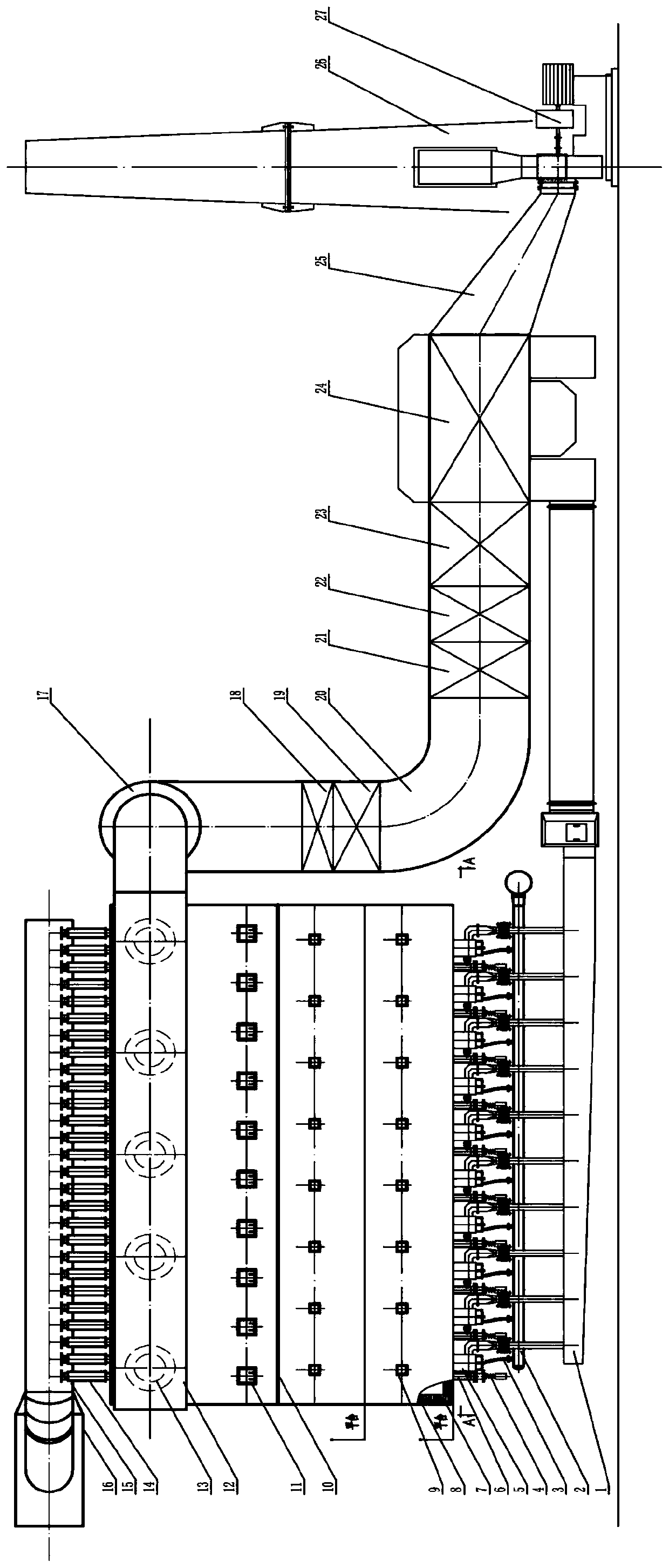
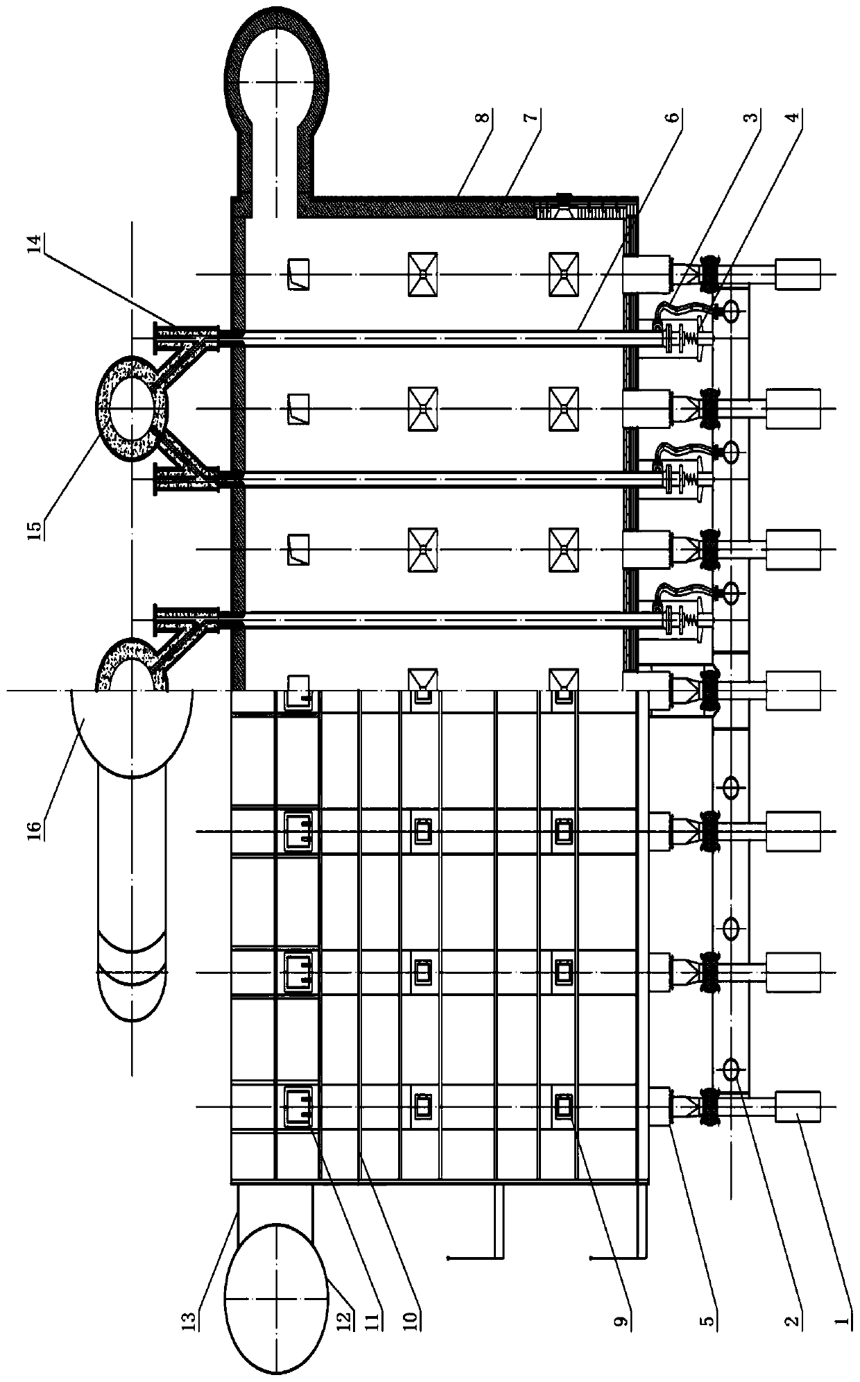
[0038] figure 1 A front view of a novel reformer showing one embodiment of the invention; figure 2 A top view of a novel reformer showing one embodiment of the present invention; image 3 A left side view of a novel reformer showing an embodiment of the present invention; Figure 4 A sectional view A-A of a novel reformer of one embodiment of the present invention is shown.

[0039] Such as figure 1 , 2 , 3, and 4, the new reformer adopts a bottom-fired structure, and the reformer tubes 6 (inner diameter ≥ 200mm) are vertically arranged inside the radiation chamber box 8, which are specifically arranged in six parallel rows. The whole furnace tube 6 passes through the roof of the radiation chamber 8 and is connected to the cold wall branch pipe 15 through the inclined tee 14. Two adjacent rows of reforming furnace tubes are connected to a cold wall branch pipe 15, and the three cold wall branch pipes are assembled at the end. Cold wall dry pipe 16, which sends the high-t...

Embodiment 2

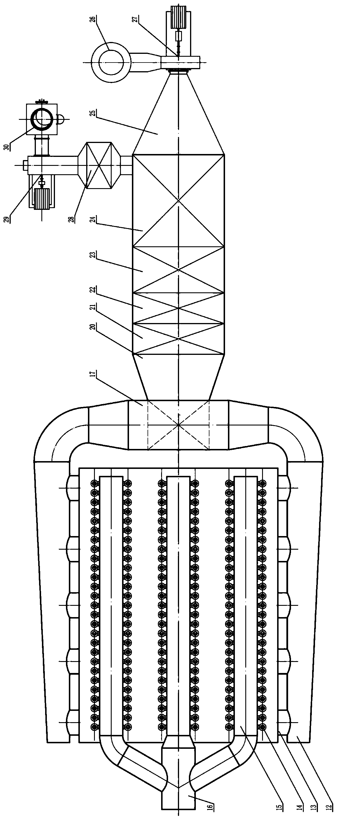
[0049] Figure 5 Shows the front view of the novel reforming furnace of Embodiment 2 of the present invention; Figure 6 A plan view of the novel reformer according to Embodiment 2 of the present invention is shown.

[0050] Such as Figure 5 , 6 As shown, the arrangement of the reformer radiation chamber, cold wall pipe, inclined tee, reforming feed gas inlet piping system and burner in this embodiment is the same as that in Embodiment 1.

[0051] The two branch main pipes 12 in the transition section are directly connected to the inlet of the convection section 20, and the convection section 20 is vertically arranged in the shape of a "1". Preheater 19, steam superheater 21, desulfurization coke oven gas preheater 22, furnace top gas preheater 23, combustion air preheater 24, heat water, raw material gas, saturated steam, coke oven in sequence through convective heat exchange Gas, furnace top gas, and air fully recover the heat of the flue gas, so that the temperature of...


PUM


Abstract

The invention provides a novel reforming furnace for preparing reducing gas, and belongs to the technical field of metallurgy and petrifaction. The reforming furnace comprises a lining radiation chamber, a reforming furnace pipe, a reforming gas port pipe system, a transition section, a convection section and an air and flue gas system. The reforming furnace pipe adopts a large caliber to reduce the furnace pipe number, so that the investment is reduced; a reforming gas inlet pipe is connected with the reforming furnace pipe by adopting a flexible pipe, so that the axial and radial heat displacements of the furnace pipe are conveniently absorbed, and the heat stress of a furnace pipe system is reduced; an elastic bracket is arranged at the bottom of the reforming furnace pipe for bearing part weight of the furnace pipe and facilitating recovery of the furnace pipe after heat expansion under the working condition of parking; a radiation chamber furnace top inclined tee joint replaces atraditional heat pipe wall, and a short tail box is canceled, so that materials are saved, and the investment is reduced; and high-temperature smoke is guided to the transition section from multiple channels at the upper parts of the two sides of the radiation chamber, and is fed in the convection section for preheating air and reforming raw material gas and fuel gas to generate high-quality vapor, so that the smoke discharge heat loss is reduced, and the heat efficiency of the reforming furnace is improved.

Description

Technical field: [0001] The invention belongs to the field of metallurgy and petrochemical technology, and relates to a novel reforming furnace for producing reducing gas. Background technique [0002] Gas-based direct reduced iron has the characteristics of short process, high efficiency and less impurities. It is a new type of advanced metallurgical steelmaking method that is different from traditional blast furnace steelmaking. At present, there is no precedent for the production of gas-based direct reduced iron in China. [0003] The main problem of gas-based reduced iron is to solve the production of reducing gas. The production of reducing gas in foreign countries mainly uses natural gas steam reforming or partial oxidation to produce synthesis gas. However, domestic natural gas resources are limited, and it is unlikely to use foreign synthetic gas production processes. In order to develop the domestic direct reduced iron industry, a new type of equipment is needed to...

Claims


Application Information

Patent Timeline
IPC IPC(8): C21B13/00C10K3/02
CPCC10K3/02C21B13/0073Y02P20/10Y02P20/129
Inventor 钱静怡张红石勇谢东升李金和顾美芳秦小燕卢志勇南卓许红平张亚新潘珍燕袁小进
Owner SINOPEC NANJING ENG & CONSTR
Why Eureka
Try Eureka